Motor and dissipation fan with the motor

A technology for cooling fans and motors, applied in the field of motors, cooling fans, and motors with metal bases, can solve the problems of uneconomical efficiency, increase the overall weight of the motor 9, and increase additional costs, so as to save metal materials and reduce the overall Weight, cost reduction effect

Active Publication Date: 2016-08-03
SUNONWEALTH ELECTRIC MACHINE IND
View PDF3 Cites 6 Cited by
  • Summary
  • Abstract
  • Description
  • Claims
  • Application Information

AI Technical Summary

Problems solved by technology

[0004] In order to achieve the main purpose of making the rotor 93 rotate smoothly, it is only necessary to ensure that the permanent magnet 932 and the metal base 91 can be magnetically attracted to each other within the magnetic attraction range D2; however, between the hub 931 and the In the radial r

Method used


Image

  • Motor and dissipation fan with the motor
  • Motor and dissipation fan with the motor
  • Motor and dissipation fan with the motor

Examples


Example Embodiment

[0048] In order to make the above and other objectives, features and advantages of the present invention more obvious and understandable, the preferred embodiments of the present invention are described in detail below in conjunction with the accompanying drawings:

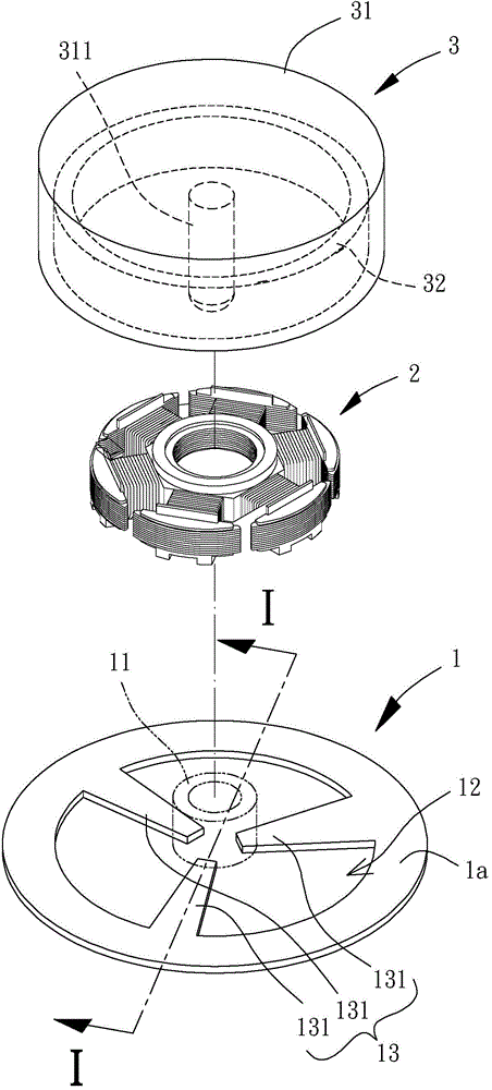
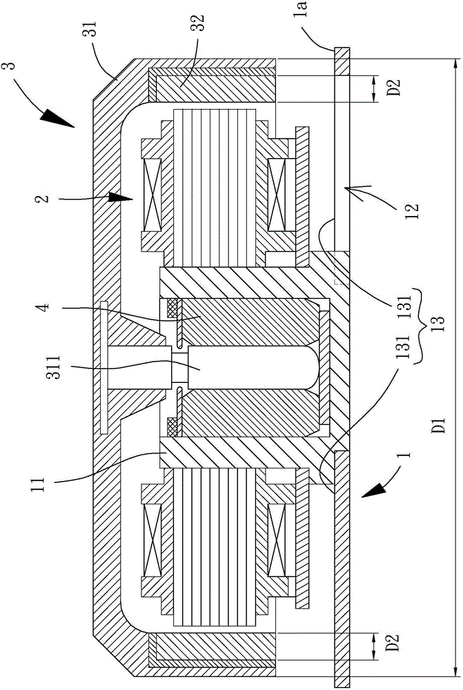
[0049] Please refer to figure 2 and image 3 As shown, the motor of the present invention includes a metal base 1, a stator 2 and a rotor 3. The metal base 1 can be used for combining the stator 2 and the rotor 3, and the stator 2 is used for driving the rotor 3 to rotate.

[0050] The metal base 1 is provided with a shaft connecting portion 11; wherein the metal base 1 is a metal member of various shapes capable of combining the stator 2 and the rotor 3, and the shaft connecting portion 11 of the metal base 1 can be It is a metal shaft tube or a plastic shaft tube, which is not limited by the present invention. It is preferably a plastic shaft tube for the arrangement of the plastic shaft tube, thereby improving the ...


PUM


Abstract

A motor comprises a metal base, a stator, and a rotor. The metal base combines with a shaft receiver. The stator combines with the metal base. The rotor comprises a hub and a permanent magnet. The hub rotatably combines with the shaft receiver. A air gap forms between the permanent magnet and the stator. Wherein, a radial rotation area forms between the hub and the metal base. A magnetic area forms between the permanent magnet and the metal base. In the radial rotation area, the metal base has an empty region between the magnetic area and the shaft receiver. The empty region has a connecting portion combined with the shaft receiver. In addition, the motor can be applied to a dissipation fan. It can reduce the weight of the motor by setting the empty region.

Description

technical field [0001] The invention relates to a motor and a cooling fan, in particular to a motor with a metal base and a cooling fan using the motor. Background technique [0002] Please refer to figure 1 As shown, a conventional motor 9 is disclosed, and the motor 9 includes a metal base 91 , a stator 92 and a rotor 93 . There is a shaft tube 911 in the center of the metal base 91; the stator 92 is combined with the outer peripheral wall of the shaft tube 911; the rotor 93 includes a hub 931 and a permanent magnet 932, and the rotor 93 is rotatably coupled to the shaft 933 Shaft tube 911, the permanent magnet 932 is arranged on the inner peripheral wall of the hub 931, and there is an air gap between the permanent magnet 932 and the stator 92; thereby, the motor 9 can be applied to a cooling fan, wherein the metal base 91 As shown in the figure, it can be used as a fan frame, and the rotor 93 can be used as a fan wheel. When the cooling fan operates, current can be inp...

Claims


Application Information

Patent Timeline
IPC IPC(8): H02K5/00H02K5/18F04D25/08F04D29/40
Inventor 洪银树
Owner SUNONWEALTH ELECTRIC MACHINE IND
Why Eureka
Try Eureka