Two-flow tube header structure of wound-tube-type heat exchanger

A heat exchanger, dual-process technology, applied in the direction of heat exchanger shell, heat exchange equipment, lighting and heating equipment, etc., can solve the problems of inconvenient maintenance and operation of equipment, complicated shell side structure, excessive opening and reinforcement, etc. Design calculation and manufacturing difficulty, reduce manufacturing difficulty and production cost, and facilitate maintenance and repair operations.

Inactive Publication Date: 2013-06-12
四川川润动力设备有限公司
View PDF5 Cites 7 Cited by
  • Summary
  • Abstract
  • Description
  • Claims
  • Application Information

AI Technical Summary

Problems solved by technology

On the one hand, this increases the difficulty of winding and threading the heat exchanger tubes, and makes the structure of the shell side more complex, making it more difficult to manufacture the shell, and also brings inconvenience to equipment maintenance operations; on the other hand, when the heat exchange tube roots of the side stream flow When the number is large, the side branch box will also increase, causing the opening reinforcement of the connection between the side branch box and the shell side to exceed the conventional opening reinforcement range, which increases the difficulty of calculation of the strength design. Design method to calculate, increase the calculation cost of the design

Method used


Image

  • Two-flow tube header structure of wound-tube-type heat exchanger
  • Two-flow tube header structure of wound-tube-type heat exchanger
  • Two-flow tube header structure of wound-tube-type heat exchanger

Examples


Embodiment 2

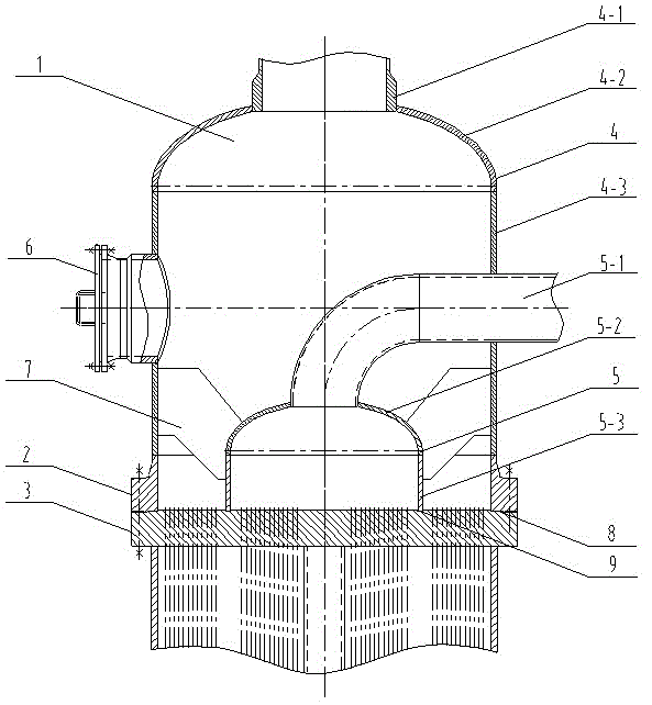
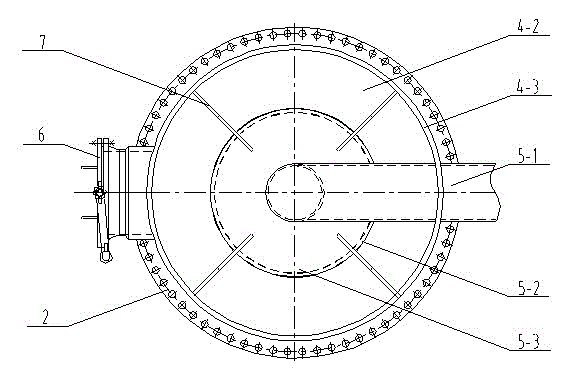
[0031] Embodiment 2, on the basis of Embodiment 1, the shape of the tube box included in the tube box structure, the number of supporting ribs and the connection position are optimized, wherein the shapes of the tube section B5-3 and the tube section A4-3 are preferably cylinders shape, it is beneficial to reduce the flow loss of the stream medium entering the pipe box in the pipe box, the integrity is good and it is easy to manufacture, and the rib plate between the head B5-2 and the barrel section B5-3 and the barrel section A4-3 The number of 7 pieces is not less than 3, preferably 3 pieces, and they are evenly arranged along the circumference of the barrel section A4-3 to ensure the stability of the connection structure of the inner and outer pipe boxes.

[0032] In actual production, the drainage design of the pipe box is usually such that the stream with high medium pressure flows through the outer pipe box, while the stream with low medium pressure flows through the inne...

Embodiment 3

[0033] Example 3, on the basis of Example 2, the mutual positional relationship between the barrel section A4-3 and the barrel section B5-3 is optimized, wherein the barrel section A4-3 and the barrel section B5-3 are concentrically arranged, and the barrel section A4-3 is arranged concentrically with the barrel section A4 -3 and the barrel section B5-3 are respectively connected to the annular sealing surface A and the annular sealing surface B on the tube sheet 3, which are also arranged concentrically with each other, that is, the barrel section A4-3, the barrel section B5-3, the annular The concentric arrangement of the sealing surface A3-1 and the annular sealing surface B3-2 is conducive to maintaining the stability of the flow drainage of the two parts of the pipe box, and it is easy to balance the pressure of the pipe box process, reducing the impact on the unbalanced pressure of the pipe box structure Security Risk. The pipes of the inner and outer tubes are arranged ...

Embodiment 4

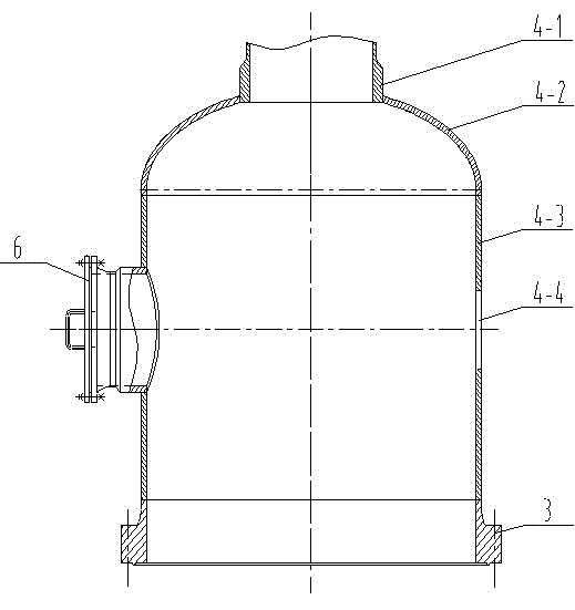
[0034] Embodiment 4, on the basis of Embodiment 1, the location of the manhole 6 is optimized, wherein the manhole 6 is located at the position of the barrel section A4-3 of the outer tube box 4 and the connecting pipe B5-1 is at the barrel section of the outer tube box 4 The lead-out position on A4-3 is right, so that it is convenient for inspectors to check the sealing of the connection parts between the inner and outer tube boxes and the annular sealing surface one by one in the left and right directions after entering the outer tube box 4 through the manhole 6, and divide them equally. The inspection surfaces on both sides of the tube box, especially the heat exchange tubes in the outer tube box process leak, the maintenance personnel can directly open the manhole 6 and enter the outer tube box 4 to quickly perform leak detection, maintenance and other operations, and can quickly and automatically The manhole 6 on the outer tube box 4 is withdrawn.


PUM


Abstract

The invention discloses a two-flow tube header structure of a wound-tube-type heat exchanger. The two-flow tube header structure comprises a tube header assembly, a flange base and a tube sheet. The tube header assembly comprises an outer tube header and an inner tube header, wherein the inner tube header and the outer tube heater respectively comprise a nozzle and a head and a cylindrical shell which are sequentially connected, the inner tube header is arranged in the outer tube header and is connected with the outer tube header through rib plates, the nozzle of the inner tube header is led out from the cylindrical shell of the outer tube header, the lower end of the cylindrical shell of the outer tube header is fixedly arranged on the flange base, two annular sealing surfaces which are arranged in the same plane are arranged on the upper end surface of the tube sheet and are respectively connected with the bottom end surface of the cylindrical shell of the inner tube header and the bottom end surface of the flange base which is connected with the bottom end of the cylindrical shell of the outer tube header, gaskets are arranged between the connected end surfaces, and the flange base is connected with the tube sheet through bolts to tightly fasten the integral inner and outer tube headers on the tube sheet. The two-flow tube header structure has the advantages that the design and manufacturing difficulty and the production cost are reduced, the unreasonable design structure with a bypass tube header on a shell side is avoided, the design calculation and the manufacturing difficulty are reduced, the overall performance is excellent, the structure is convenient to assemble and the operation for maintenance, inspection, repair and the like is easy to conduct.

Description

technical field [0001] The invention relates to the technical field of chemical pressure vessels, in particular to a double-flow pipe box structure of a winding heat exchanger. Background technique [0002] Winding heat exchanger is a new type of high-efficiency heat exchanger developed in recent years. It is widely used in the heating or cooling process of coal chemical industry, methanol and other industries. In the industry, it is classified according to the fluid flow in the heat exchanger, usually The shell side fluid is regarded as a stream, therefore, the single stream heat exchanger does not exist; the double stream heat exchanger, one stream flows through the shell side, and the other stream flows through the tube side; the three stream heat exchanger, one stream One flow goes through the shell side, and the other two flows through the tube side; for four-flow heat exchangers, one flow goes through the shell side, and the other three flows through the tube side, and...

Claims


Application Information

Patent Timeline
Patent Type & Authority Applications(China)
IPC IPC(8): F28F9/02F28F9/18F28F9/10
Inventor 饶谋生胡大鹏易树春
Owner 四川川润动力设备有限公司
Why Eureka
Try Eureka