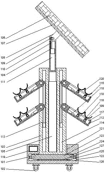
A mobile power generation device
A mobile power generation and equipment technology, applied in photovoltaic power generation, electrical components, photovoltaic modules, etc., can solve the problems of immobility, single structure, and aesthetic impact, and achieve the effect of convenient movement and beautiful environment
- Summary
- Abstract
- Description
- Claims
- Application Information
AI Technical Summary
Problems solved by technology
Method used
Image
Examples
Embodiment 1
[0025] Such as figure 1 As shown, a mobile power generation equipment includes a mobile support 101 and a photovoltaic panel 106 arranged above the mobile support, and a roller 102 is arranged below the mobile support. An outer layer bracket 103 is arranged above, an inner layer bracket 104 is arranged inside the outer layer bracket, and a bracket lifting device 105 is arranged at the bottom of the inner layer bracket;
[0026] A groove is arranged on the top of the inner support, a fixed frame 107 is arranged on the lower end surface of the photovoltaic panel, and a fixed flange 108 is arranged in the middle of the fixed frame, and the fixed flange is inserted into the Connected to the inner side of the groove, the fixed flange is rotatably connected to the top of the inner support through a rotating shaft passing through the groove, and a photovoltaic panel pushing device 111 is arranged in the middle of the inner support , a rack 110 is provided on the photovoltaic panel p...
Embodiment 2
[0032] In this embodiment, on the basis of Embodiment 1, in order to place plants conveniently, preferably, a plant tray 115 for placing plants is provided on the flower stand.
[0033] Further preferably, in order to facilitate the installation of the plant tray as required, in this embodiment, a card slot 117 is provided inside the flower stand, and a pole 116 is provided below the plant tray, and the pole 116 is inserted into the Inside the draw-in slot, the support rod is rotatably connected in the draw-in slot through a rotating shaft passing through the draw-in slot. Secure the plant tray to the flower stand with the poles.
[0034] Since the angle of the plant tray may not be suitable for placing potted plants after the angle of the flower stand is adjusted, in this embodiment, in order to improve this problem, preferably, a tray pushing device 118 is provided at the bottom of the slot, The pushing device is provided with a rack 110, and the rack is in mesh with the ge...
Embodiment 3
[0037] In this embodiment, on the basis of Embodiment 1 or 2, in order to facilitate the fixing of the outer support, preferably, a fixing groove is provided on the mobile support, and the lower end of the outer support is plugged into the inside the fixing slot.
[0038] Further preferably, in order to make the outer support more stable, in this embodiment, the cross section of the fixing groove is an inverted T-shaped structure, and the fixing groove includes an upper vertical part 121 and a lower horizontal part 122, A fixed base 123 is provided at the lower end of the outer support, and the fixed base is located inside the horizontal part.
[0039]In order to make the overall structure relatively stable when it is subjected to a force in the horizontal direction, in this embodiment, preferably, buffer blocks 124 are respectively provided on the two opposite end faces of the horizontal part. The side end face faces the side wall of the fixed base, and a return spring 125 i...
PUM
 Abstract
Description
Claims
Application Information
 - R&D
- Intellectual Property
- Life Sciences
- Materials
- Tech Scout
- Unparalleled Data Quality
- Higher Quality Content
- 60% Fewer Hallucinations
Browse by: Latest US Patents, China's latest patents, Technical Efficacy Thesaurus, Application Domain, Technology Topic, Popular Technical Reports.
© 2025 PatSnap. All rights reserved.Legal|Privacy policy|Modern Slavery Act Transparency Statement|Sitemap|About US| Contact US: help@patsnap.com

