
Roller support reciprocated driving device for high-speed cold pilger mill

A reciprocating driving device, cold rolling mill technology, applied in the direction of the driving device for metal rolling mills, metal rolling, metal rolling, etc., can solve the problem that the speed of rolling tubes is difficult to achieve, the production capacity of steel tubes cannot be obtained, and the reciprocation of partial waste roll stands Movement speed and other issues to achieve the effect of improving rolling capacity

Active Publication Date: 2016-08-10
CHANGSHU MEILI MACHINERY MFG
View PDF17 Cites 1 Cited by
  • Summary
  • Abstract
  • Description
  • Claims
  • Application Information

AI Technical Summary

Problems solved by technology

[0005] Furthermore, as known in the industry, the production capacity of steel pipes depends to a large extent on the rolling speed of steel pipes, and the reciprocating speed of the roll stand needs to adapt to the speed of motion of the rolls that are rotatably arranged on the roll stand, that is to say It is impossible to obtain the steel pipe production capacity expected by the industry only by increasing the speed of the roll and ignoring the reciprocating speed of the roll stand
[0006] Because the roll stand reciprocating drive device in the prior art drives the roll stand to reciprocate at a speed of 70-80 times / min, it is difficult to achieve the expected speed of rolling tubes, because 70-80 times / min represents a low-speed motion

Method used


Image

  • Roller support reciprocated driving device for high-speed cold pilger mill

Examples


Embodiment Construction

[0020] In order to facilitate a clearer understanding of the technical essence and beneficial effects of the present invention, the applicant will describe in detail below by way of examples, but the description of the examples is not intended to limit the solution of the present invention, and any Equivalent transformations that are only formal but not substantial should be regarded as the scope of the technical solutions of the present invention.

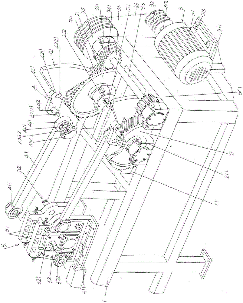
[0021] See figure 1 , shows a frame 1 with a frame-like structure; a pair of large gears 2 are rotatably supported on the right end of the frame 1 through a large gear half shaft 21 in a state corresponding to each other; a large gear drive mechanism 3 is shown , the large gear drive mechanism 3 is arranged on the frame 1 at a position corresponding to the right side of the aforementioned pair of large gears 2 and is in driving cooperation with the pair of large gears 2; a pair of connected A lever mechanism 4, the pair of link m...


PUM


Abstract

The invention relates to a roller support reciprocated driving device for a high-speed cold pilger mill, and belongs to the technical field of steel tube rolling machines. The roller support reciprocated driving device comprises a rack, a pair of large gears, a large gear driving mechanism and a pair of connecting rod mechanisms; the pair of large gears are supported to the right end of the rack through large gear axle shafts in the mutually-corresponding manner; the large gear driving mechanism is arranged at the position, corresponding to the right sides of the pair of large gears, on the rack and is in transmission fit with the pair of large gears; and the pair of connecting rod mechanisms are connected with the large gear axle shafts of the pair of large gears and are connected with a roller support movably arranged at the upper portion of the left end of the rack. The roller support reciprocated driving device is characterized in that each of the pair of connecting rod mechanism comprises a connecting rod and a balance hammer, each balance hammer and the corresponding large gear axle shaft are fixed, the left end of each connecting rod is connected with the roller support, and the right end of each connecting rod is connected with the corresponding balance hammer. The motion speed of the pair of connecting rods can be increased, and the steel tube rolling capacity within unit time can be better improved remarkably.

Description

technical field [0001] The invention belongs to the technical field of steel pipe rolling machinery, and in particular relates to a reciprocating driving device of a roll stand of a high-speed cold-rolling pipe mill. Background technique [0002] Cold rolling mill is a special equipment for cold rolling by using perforated tubes (also known as capillary tubes or blank tubes), because of its excellent blanking performance and the ability to roll non-ferrous metal seamless tubes with good viscosity, The high material utilization rate and the surface roughness are significantly better than those of cold drawn pipes, so they are widely used in the steel pipe manufacturing industry. [0003] As known in the industry, a complete set of pipe rolling mills usually includes a conveying device, a feeding device (such as patents CN102059261B, CN10343300B), a steel pipe rotating device (such as CN103433305B, CN104107835A), a rolling device and an output device. The rolling device mainl...

Claims


Application Information

Patent Timeline
Patent Type & Authority Applications(China)
IPC IPC(8): B21B35/12
CPCB21B35/12
Inventor 王伟陈东武薛志军吕斌
Owner CHANGSHU MEILI MACHINERY MFG
Learn More