Clamp

A technology of fixtures and claws, which is applied in the field of fixtures, can solve problems such as insufficient fast and convenient adjustment of the clamp distance, inconvenient parts replacement and maintenance operations, and inability to replace the movable cover of the claws online, etc., to achieve optimal fit, convenient operation, and convenient operation Effect

Active Publication Date: 2016-08-10
曹正虎
View PDF7 Cites 31 Cited by
  • Summary
  • Abstract
  • Description
  • Claims
  • Application Information

AI Technical Summary

Problems solved by technology

Although this fixture greatly reduces labor intensity, improves the clamping and unloading efficiency of the workpiece, and the clamping distance is adjustable, there are still deficiencies: first, the installation and disassembly of the fixture are troublesome, and the replacement and maintenance of parts are inconvenient; , the adjustment of the clamp distance of the fixture is not fast and convenient; in addition, the movable cover of the jaws of the fixture cannot be replaced online, and when it needs to be replaced, the entire shell and internal parts need to be disassembled and replaced, which is inconvenient to operate

Method used


Image

  • Clamp
  • Clamp
  • Clamp

Examples


Embodiment Construction

[0025] The specific implementation manners of the present invention will be further described in detail below in conjunction with the accompanying drawings and embodiments. The following examples are used to illustrate the present invention, but are not intended to limit the scope of the present invention.

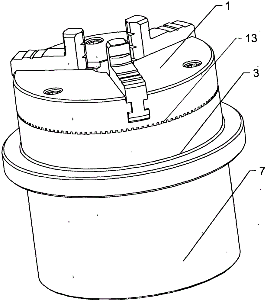
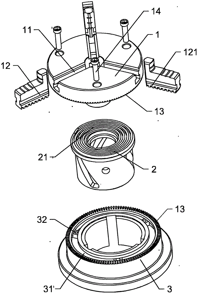
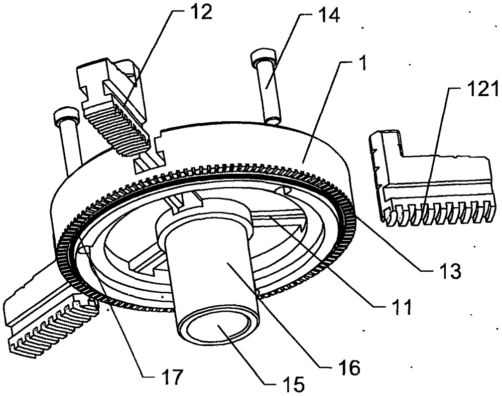
[0026] Such as figure 1 and figure 2 As shown, a clamp includes a shell and a spiral disc 2, the shell includes a claw movable cover 1, the center of the claw movable cover 1 is provided with a through hole 15, and the cover surface of the claw movable cover 1 There are three running rails 11 that communicate with the through hole 15 and pass through the side of the cover. Each running rail 11 is provided with a claw 12 for sliding movement. The spiral disk 2 is installed in the claw movable cover 1. The surface of the disc 2 is provided with a spiral groove 21, and the back of the jaw 12 is provided with a helical tooth 121 that cooperates with the helical groove 21. T...


PUM


Abstract

The invention provides a clamp. The clamp comprises a shell and a spiral disc; the shell comprises a clamping jaw movable cover, and further comprises a positioning sleeve detachably connected with the clamping jaw movable cover, and the positioning sleeve is provided with a plurality of sliding blocks capable of sliding in the circumferential direction; the clamping jaw movable cover is provided with screws capable of being in matched connection with the sliding blocks, and the clamping jaw movable cover and the positioning sleeve are in axial fixation through the screws; and the end face, in contact with the clamping jaw movable cover, of the positioning sleeve is provided with a positioning assembly playing a role in circumferential fixation of the clamping jaw movable cover and the positioning sleeve, and the screws can enable spiral teeth and spiral grooves to keep in linkage fit when the clamping jaw movable cover circumferentially rotates on the positioning sleeve. By means of the clamp, clamp modularization combination is achieved, assembling and disassembling are convenient, the clamping jaw clip distance is conveniently adjusted, the clamping jaw movable cover can be replaced, and the clamp integrating a clamp air cylinder can be achieved.

Description

technical field [0001] The invention relates to a fixture, in particular to a fixture suitable for machines such as bench drills, vertical drills, milling machines, and numerical control engraving and milling. Background technique [0002] Fixtures are used in mechanical lathes to clamp workpieces and then process them. The structure of the existing lathe clamps generally includes a jaw movable cover and a spiral disk. A through hole is arranged in the center of the jaw movable cover, and a walking rail connected with the through hole is arranged on the cover surface of the jaw movable cover. Claws are provided for sliding on the walking rail, and the back of the claws are provided with helical tooth grooves that are helically matched with the helical disk. Through the rotation of the spiral disc, the claws can slide toward each other or relative to each other in the traveling rail, so as to realize the clamping and unloading of the workpiece. [0003] The applicant earlie...

Claims


Application Information

Patent Timeline
Patent Type & Authority Applications(China)
IPC IPC(8): B23Q3/00
CPCB23Q3/00B23Q2703/04
Inventor 曹正虎
Owner 曹正虎
Why Eureka
Try Eureka