Calibration method for large-area optical profilometry based on dual-wavefront interference fringe array

A technology of interference fringe and contour measurement, which is applied in the direction of measuring devices, optical devices, instruments, etc., can solve the problems of increased cost, inability to measure, and inability to obtain very thin fringes, so as to reduce the number of calibrations and achieve simple and efficient measurement Calibration effect

Inactive Publication Date: 2018-03-27
UNIV OF ELECTRONICS SCI & TECH OF CHINA
View PDF3 Cites 0 Cited by
  • Summary
  • Abstract
  • Description
  • Claims
  • Application Information

AI Technical Summary

Problems solved by technology

The disadvantages of this method are as follows: 1) the quality of the projected grating directly affects the accuracy of detection in this method, requiring high grating resolution and good uniformity of projected light, etc., which increase the cost, and the accuracy of projection is unreasonable 2) Due to the limitation of the projection fringes of the projection grating, this method cannot obtain very thin fringes, so for some small objects, this method cannot be measured; 3) There are a lot of data in the calculation that need to be measured manually, and the measurement is accurate Whether or not it will also affect the final result
The shortcoming of this method has: 1) the line laser mobile scanning measurement method needs to pass through the moving time of a period of time, so the real-time performance of measurement is poor, does not realize real-time work; 2) line laser mobile scanning measurement method needs special mobile platform, mobile The platform requires precise control and increases the cost

Method used


Image

  • Calibration method for large-area optical profilometry based on dual-wavefront interference fringe array
  • Calibration method for large-area optical profilometry based on dual-wavefront interference fringe array
  • Calibration method for large-area optical profilometry based on dual-wavefront interference fringe array

Examples


Embodiment Construction

[0029] In order to make the object, technical solution and advantages of the present invention clearer, the present invention will be further described in detail below in conjunction with the accompanying drawings and embodiments. It should be understood that the specific embodiments described here are only used to explain the present invention, not to limit the present invention.

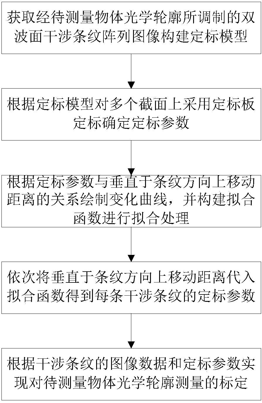
[0030] Such as figure 1 As shown, it is a schematic flowchart of the large-area optical profilometry calibration method based on the double-wavefront interference fringe array of the present invention. A calibration method for large-area optical profilometry based on a double-wavefront interference fringe array, comprising the following steps:

[0031] A. Obtain the double-wavefront interference fringe array image modulated by the optical profile of the object to be measured, and construct a calibration model according to the mapping relationship between the calibration plate image coordinate syst...


PUM


Abstract

The invention discloses a large-area optical profilometer calibration method based on a double-wavefront interference fringe array; it comprises acquiring a double-wavefront interference fringe array image modulated by the optical profile of an object to be measured, and constructing a calibration model; Use the calibration plate to calibrate multiple sections, and determine the calibration parameters; draw the change curve according to the calibration parameters, and construct a fitting function for fitting processing; sequentially substitute the moving distance of adjacent interference fringes perpendicular to the fringe direction into The fitting function obtains the calibration parameters of each interference fringe; the real shape of each section is restored according to the image data of the interference fringes and the calibration parameters, and the calibration of the optical profile measurement of the object to be measured is realized. The present invention constructs a calibration model of a double-wavefront interference fringe array image, and uses a fitting method to determine the calibration parameters in the calibration model of each interference fringe, greatly reducing the number of calibrations, and realizing large-area optical profile measurement simply and efficiently calibration.

Description

technical field [0001] The invention belongs to the technical field of three-dimensional object measurement, and in particular relates to a calibration method for large-area optical profilometry based on a double-wavefront interference fringe array. Background technique [0002] With the development of computer technology, it has been a dream of human beings for many years to endow computers, robots and other intelligent machines with human visual functions. Therefore, the theory and technology of computer vision have been developed rapidly. Computer vision technology is widely used in scientific research, national defense construction and national economy and other fields. It has the incomparable advantages of human vision, which is manifested in the non-contact with the measured object, greatly expanding the range of human vision, and being able to work in harsh environments for a long time. The main visual measurement technology based on computer vision theory The task ...

Claims


Application Information

Patent Timeline
Patent Type & Authority Patents(China)
IPC IPC(8): G01B11/24
CPCG01B11/2441
Inventor 余学才王晓庞肖景天任华西
Owner UNIV OF ELECTRONICS SCI & TECH OF CHINA
Why Eureka
Try Eureka