Identifier code making method, camera module and electronic device

A production method and a camera module technology, which are applied to televisions, color televisions, electrical components, etc., can solve the problems of low alignment accuracy and deviation of identification codes, and achieve high alignment accuracy

Active Publication Date: 2016-08-10
TRULY OPTO ELECTRONICS
View PDF5 Cites 4 Cited by
  • Summary
  • Abstract
  • Description
  • Claims
  • Application Information

AI Technical Summary

Problems solved by technology

[0004] In view of this, the present invention provides a method for making an identification code, a camera module and an electronic device to solve the problem in the prior art that the identification code is displaced due to the low alignment accuracy of the metal alignment mark

Method used


Image

  • Identifier code making method, camera module and electronic device
  • Identifier code making method, camera module and electronic device
  • Identifier code making method, camera module and electronic device

Examples


Embodiment Construction

[0024] The following will clearly and completely describe the technical solutions in the embodiments of the present invention with reference to the accompanying drawings in the embodiments of the present invention. Obviously, the described embodiments are only some, not all, embodiments of the present invention. Based on the embodiments of the present invention, all other embodiments obtained by persons of ordinary skill in the art without making creative efforts belong to the protection scope of the present invention.

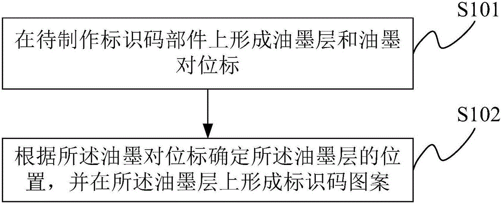
[0025] An embodiment of the present invention provides a method for making an identification code, which is applied to form an identification code on a camera module. The identification code is an identity code of the camera module and is used for product tracking and tracing. Wherein, the identification code may be a two-dimensional code, or a barcode, etc., which is not limited in the present invention.

[0026] Such as figure 1 As shown, the process flow o...


PUM


Abstract

The invention provides an identifier code making method, a camera module and an electronic device. The identifier code making method includes the steps of forming an ink layer and an ink aligning marker on a part where an identifier code is to be made, determining the position of the ink layer according to the ink aligning marker and forming identifier code patterns on the ink layer, wherein the ink layer and the ink aligning marker are on the same layer, and the distance between the ink layer and the ink aligning marker is fixed. The ink layer and the ink aligning marker are formed at the same time, and the distance between the ink layer and the ink aligning marker is fixed, i.e. when the position of the ink layer deviates, the position of the ink aligning marker deviates accordingly with the corresponding distance. The ink aligning marker can still accurately determines the position of the ink layer, deviation of the ink aligning marker can be prevented, and aligning precision is high.

Description

technical field [0001] The invention relates to the technical field of camera modules, and more specifically, to a method for making an identification code, a camera module and electronic equipment. Background technique [0002] At present, more and more camera modules require identification codes (such as QR codes) to facilitate product tracking and tracing. In the prior art, when making the identification code, a layer of ink is screen-printed on the ink area on the metal layer of the main circuit board of the camera module, that is, PCB (Printed Circuit Board, flexible circuit board), and then according to the metal on the metal layer. The position mark determines the position of the ink area, and finally the identification code pattern is made on the ink of the ink area. [0003] However, since the screen printed ink often deviates from the ink area when printing ink, and the position of the metal alignment mark is fixed, if the position of the ink is still determined a...

Claims


Application Information

Patent Timeline
Patent Type & Authority Applications(China)
IPC IPC(8): G06K19/06G09F3/00H04N5/225
CPCG06K19/06037G09F3/0297H04N23/54H04N23/55
Inventor 温美梅李建华
Owner TRULY OPTO ELECTRONICS
Why Eureka
Try Eureka