Power splicing fitting having good wire clamping fastness
A technology for connecting fittings and clamping wires. It is applied in the direction of conductive connection, electrical component connection, clamping/spring connection, etc. It can solve the problems of poor firmness and easy loosening, and achieve vibration reduction, reasonable center of gravity distribution, and excellent anti-loosening effect. Effect
- Summary
- Abstract
- Description
- Claims
- Application Information
AI Technical Summary
Problems solved by technology
Method used
Image

Examples
Embodiment 1)
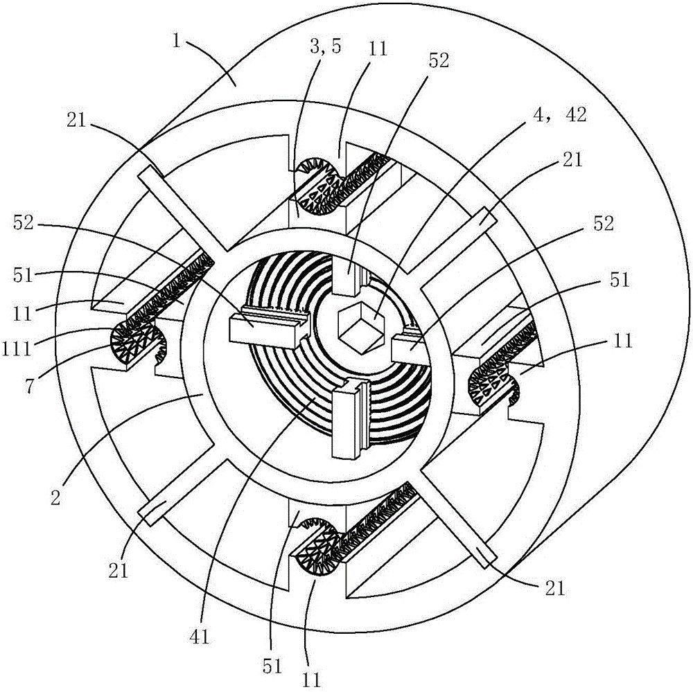
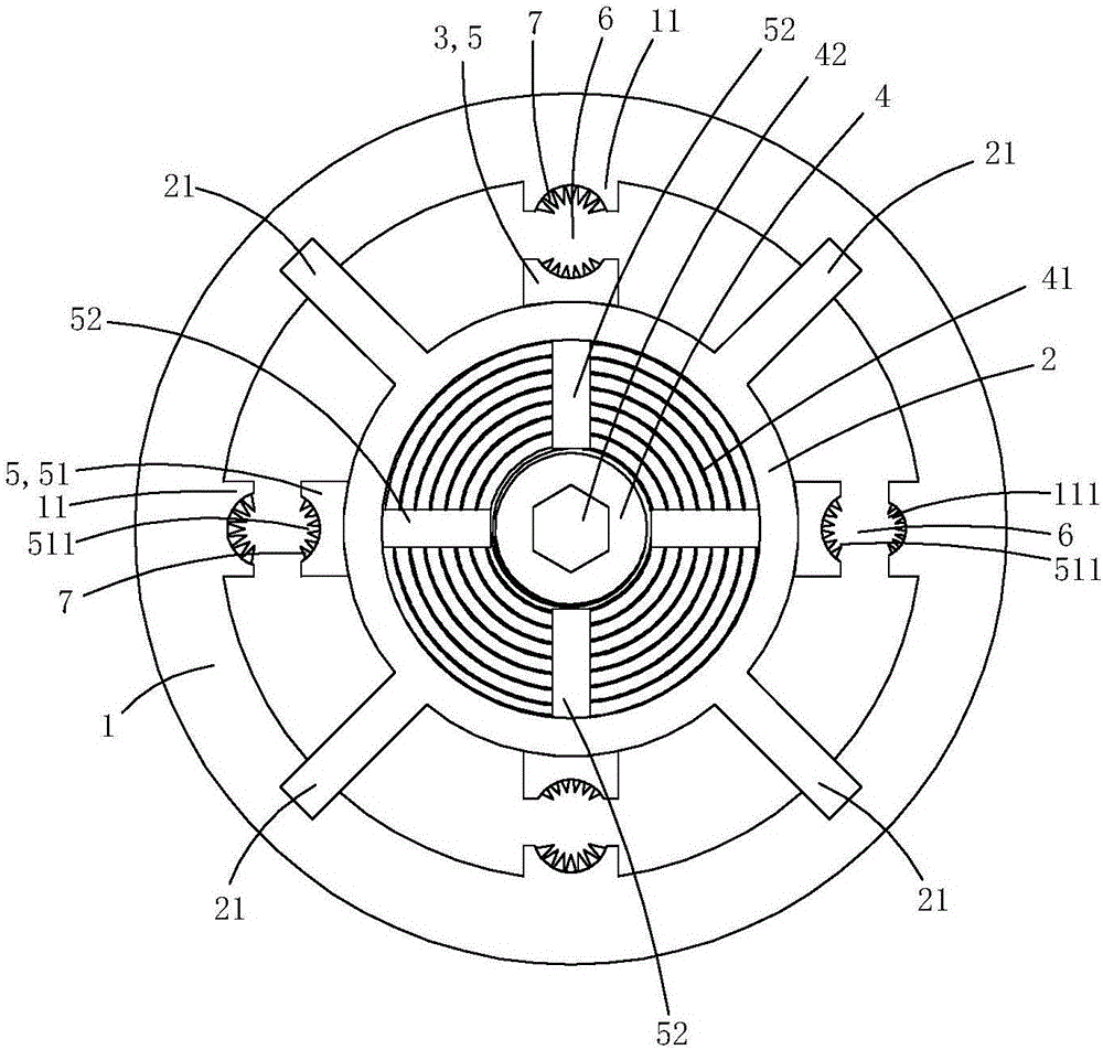
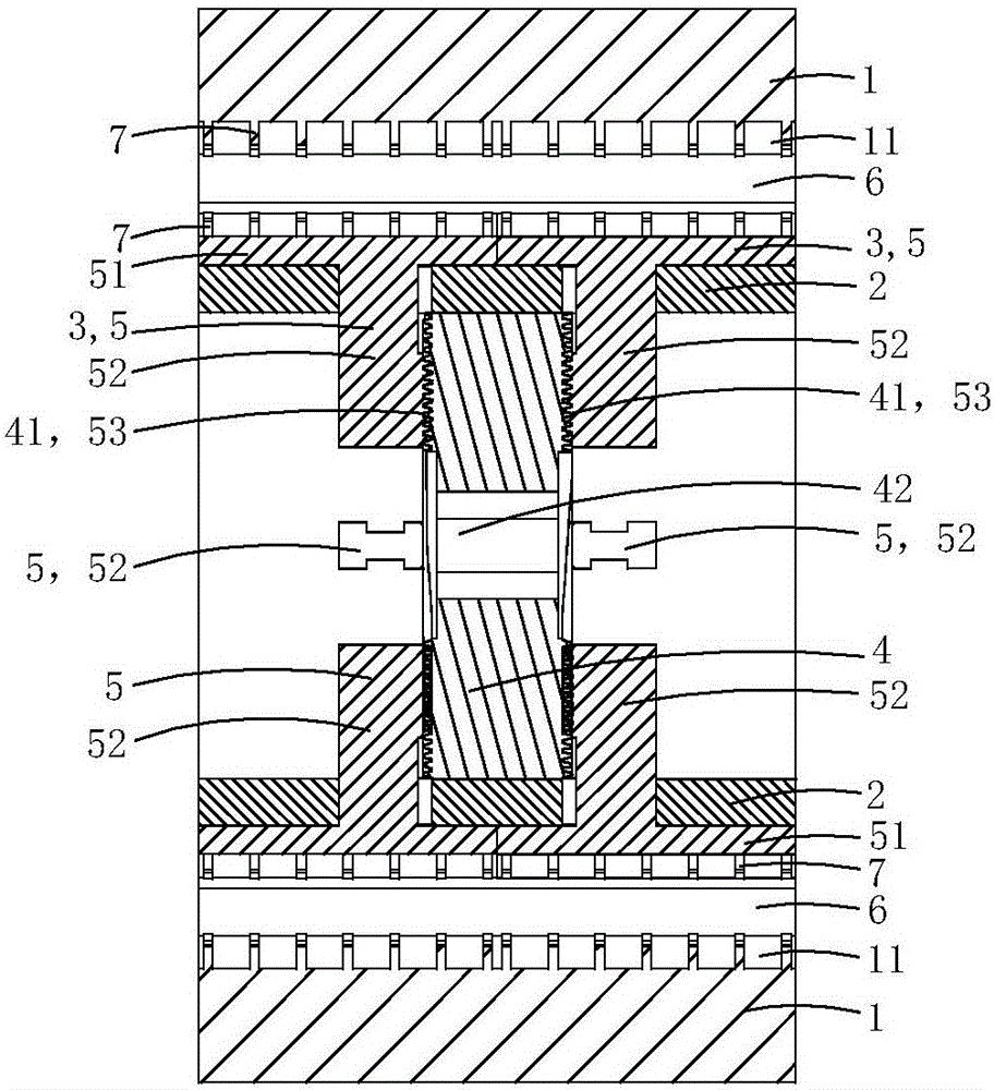
[0019] This embodiment is a kind of electric power connection fittings with better clamping fastness, see Figure 1 to Figure 5 As shown, it includes a base pipe 1 , a core pipe 2 , two sets of pressing jaw assemblies 3 and a flat nut 4 .
[0020] The inner peripheral wall of the substrate tube is provided with a plurality of crimping bosses 11 along the axial direction of the substrate tube, and the inner wall of each crimping boss is provided with arc-shaped grooves 111; the inner peripheral wall of the substrate tube is also provided with a plurality of positioning The chute 12; the core tube and the base tube are arranged concentrically and are located in the lumen of the base tube; the outer peripheral wall of the core tube is provided with a plurality of supporting convex plates 21 extending radially along the core tube, and the outer ends of each supporting convex plate Located in a corresponding positioning chute, so that the core tube is supported and positioned in th...
Embodiment 2)
[0033] This embodiment is basically the same as Embodiment 1, the difference is: see Figure 6 and Figure 7 As shown, the base pipe 1 is provided with a mounting screw hole 15 radially penetrating through the wall of the base pipe; a temperature sensing device 8 is fixed in the mounting screw hole.
[0034] The temperature sensing device 8 includes a metal housing 81 made of metal material with a containing groove 811, a temperature sensor 82 arranged in the containing groove, and a spring 83 for crimping the temperature sensor on the bottom wall of the containing groove , The screw tube plug 84 that is used for limit spring.
[0035] One end 812 of the metal shell close to the central axis of the core tube is provided with a heat conduction boss 813 used as a puncture, and one end 814 of the metal shell away from the central axis of the core tube is provided with an inner hexagonal screw groove 815; There is an external thread 816 adapted to the mounting screw hole, and an...
Embodiment 3)
[0043] This embodiment is basically the same as Embodiment 2, the difference is: see Figure 8 As shown, a current transformer 9 is sleeved and fixed on the outer peripheral wall of the base pipe in this embodiment, and the current transformer 9 includes a ring-shaped induction body 91 and an intelligent control module 92; the overall shape of the intelligent control module is also ring-shaped; the ring-shaped induction The main body 91 and the intelligent control module 92 are arranged side by side.
[0044] The inner peripheral wall of the intelligent control module 92 is provided with two sockets protruding inward (not shown in the figure), and each socket is inserted into a corresponding socket, so that the temperature sensor and the intelligent control module connected to the central control circuit in the
[0045] When the number of crimping bosses and pressing claws in this embodiment is three, this embodiment can form three clamping holes for clamping three phase cabl...
PUM
 Abstract
Description
Claims
Application Information
 - R&D
- Intellectual Property
- Life Sciences
- Materials
- Tech Scout
- Unparalleled Data Quality
- Higher Quality Content
- 60% Fewer Hallucinations
Browse by: Latest US Patents, China's latest patents, Technical Efficacy Thesaurus, Application Domain, Technology Topic, Popular Technical Reports.
© 2025 PatSnap. All rights reserved.Legal|Privacy policy|Modern Slavery Act Transparency Statement|Sitemap|About US| Contact US: help@patsnap.com