Permanent magnet rotating core and motor rotor employing same

A technology for motor rotors and permanent magnets, applied in the direction of magnetic circuit rotating parts, magnetic circuits, electrical components, etc., can solve the problems of inability to stretch the rotor sleeve, easy cracking, etc., to facilitate processing and production, enhance radial fixing force, The effect of structural stability

Inactive Publication Date: 2016-08-10
FOSHAN HANTESEN MOTOR CO LTD
View PDF8 Cites 5 Cited by
  • Summary
  • Abstract
  • Description
  • Claims
  • Application Information

AI Technical Summary

Problems solved by technology

The former has welding seams and sand holes, which are easy to crack, and the latter cannot be stretch

Method used


Image

  • Permanent magnet rotating core and motor rotor employing same
  • Permanent magnet rotating core and motor rotor employing same
  • Permanent magnet rotating core and motor rotor employing same

Examples


Embodiment Construction

[0021] The technical solutions of the present invention will be further described below in conjunction with the accompanying drawings and through specific implementation methods.

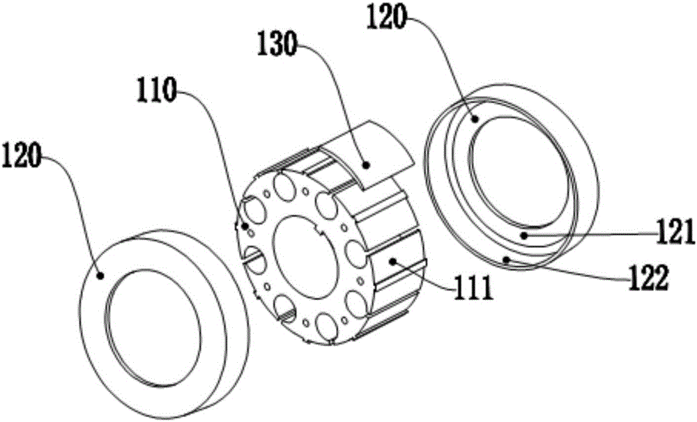
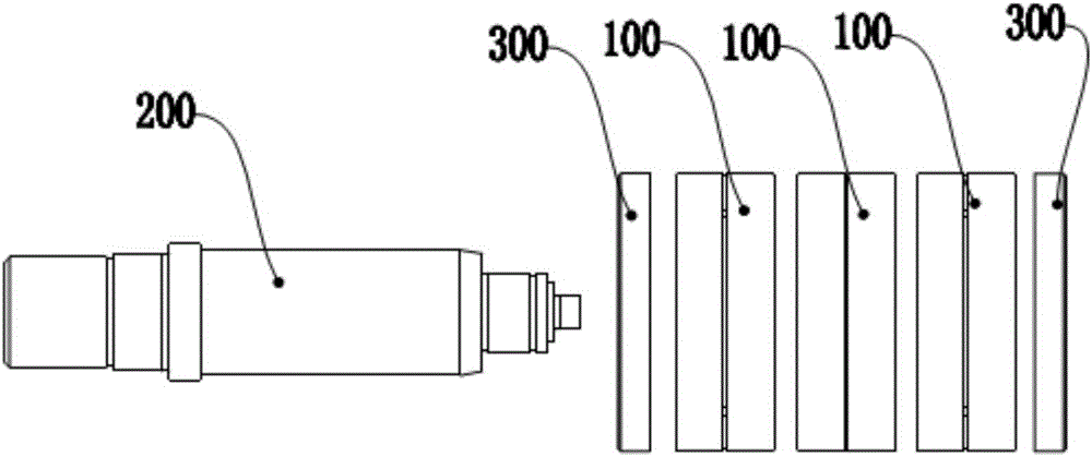
[0022] Such as Figure 1-2 As shown, a permanent magnet rotor includes a rotor group composed of two or more segmented rotors 100; the segmented rotor includes a rotor core 110, a rotor sleeve 120 and a permanent magnet 130; the rotor sleeve 120 includes a bottom plate 121 and a ring wall 122, the bottom plate 121 is an annular plate structure, the ring wall 122 is a cylindrical structure; the bottom plate 121 is located at the end of the ring wall 122, and its outer ring is connected to the Ring wall connection; the rotor core 110 is an annular columnar structure; the permanent magnet 130 is an arc-shaped sheet structure, and the permanent magnet 130 is fixed on the outer surface of the rotor core 110; the rotor sleeve 120 is two , covering and attaching to the rotor core 110 from the two end surf...


PUM


Abstract

The invention relates to the technical field of motors and specifically relates to a permanent magnet structure and a motor rotor employing the same. The permanent magnet structure comprises a rotor group consisting of two or more than two segmented rotors; each segmented rotor comprises a rotor iron core, two rotor sleeves and a permanent magnet; the rotor sleeve comprises a base plate and an annular wall, the base plate has an annular plate-shaped structure, the annular wall has a cylindrical structure, the permanent magnet is fixed on an outer surface of the rotor iron core, the two rotor sleeves sleeve on two end faces of the rotor iron core in an attached manner, and the rotor sleeves are enabled to fix the permanent magnet on the rotor iron core radially and axially; the rotor sleeves, the permanent magnet and the rotor iron core are assembled into one unit and are easy to install; the rotor sleeves are sleeve cylinders having annular bottoms, and the rotor sleeves are shorter and smaller than welded drums and stretching whole cylinders and are easy to process and manufacture.

Description

technical field [0001] The invention relates to the technical field of motors, in particular to a permanent magnet structure and a motor rotor using it. Background technique [0002] At present, there are two kinds of fixed structure schemes for the rotor permanent magnets of AC permanent magnet motors. One is the built-in structure. The rotor core is slotted inside. The permanent magnets are designed in a square shape and inserted into the rotor core for tangential and radial fixation. Press into the end plate for axial fixation; the second is the surface mount structure, the surface of the rotor core is grooved, the permanent magnet is attached to the rotor core for tangential fixation, both ends are pressed into the end plate for axial fixation, and the entire outer circle is pressed into The overall cylindrical stainless steel rotor sleeve is fixed radially. [0003] There are usually two types of full-tube rotors wrapped by the outer circle of the rotor. One is to roll...

Claims


Application Information

Patent Timeline
IPC IPC(8): H02K1/27
CPCH02K1/27H02K1/274
Inventor 刘海周彪
Owner FOSHAN HANTESEN MOTOR CO LTD
Why Eureka
Try Eureka