Check patentability & draft patents in minutes with Patsnap Eureka AI!

Dispersion machine with material scraping and uniform stirring functions

A disperser and functional technology, applied in mixers with rotary stirring devices, mixer accessories, mixers, etc., can solve the problems of inability to be further stirred and dispersed, poor stirring and dispersing effect of the disperser, and adhesion of slurry raw materials, etc. Achieve the effect of improving stirring and dispersing effect, absorbing vibration and avoiding pollution

Inactive Publication Date: 2016-08-17
YICHENG BARRIER ZHANGJIAGANG TECH CO LTD
View PDF7 Cites 1 Cited by
  • Summary
  • Abstract
  • Description
  • Claims
  • Application Information

AI Technical Summary

Problems solved by technology

[0003] The disperser with the above structure has the following disadvantages: during the working process of the disperser, the slurry raw material in the material tank 107 will gradually spread to the peripheral area of ​​the material tank 107 due to the shear force generated by the high-speed rotating dispersing disc 104, resulting in a part Slurry raw materials that have not been completely dissolved adhere to the inner wall of the bucket 107 and cannot be further stirred and dispersed, which will lead to poor stirring and dispersing effect of the disperser
Therefore in the work, it is often necessary for the operator to stand on the edge of the mouth of the bucket 107 with a stirring rod in hand, and constantly scrape off the raw materials adhered to the inner wall of the bucket 107. The operation is very cumbersome and the work efficiency is low; Risk of accidentally falling into the tank

Method used


Image

  • Dispersion machine with material scraping and uniform stirring functions
  • Dispersion machine with material scraping and uniform stirring functions
  • Dispersion machine with material scraping and uniform stirring functions

Examples


Embodiment Construction

[0015] The technical solutions of the present invention will be further described in detail below in conjunction with the accompanying drawings and preferred embodiments.

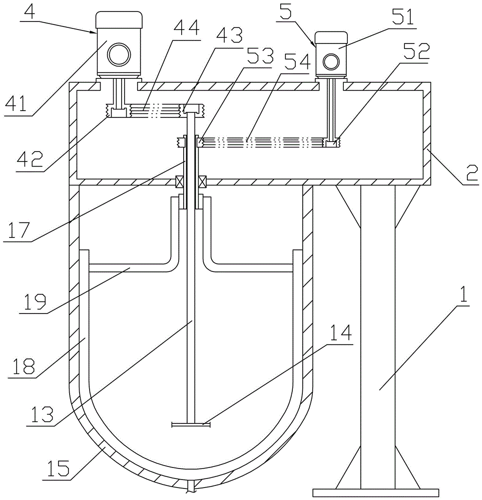
[0016] Such as figure 2 As shown, the dispersing machine with the function of scraping and stirring includes: a frame 1, a horizontally protruding suspension beam frame 2 is arranged on the frame 1, and a main shaft 13 is movably supported in the suspension beam support 2, and the lower end of the main shaft 13 is vertically The suspension beam frame 2 protrudes from the bottom, the lower end of the main shaft 13 is fixedly covered with a dispersing disc 14, and the suspension beam frame 2 is provided with a main driving device 4 for driving the rotation of the main shaft 13. In this embodiment, the specific structure of the main drive device 4 includes: a main drive motor 41 is arranged on the suspension beam frame 2, a drive wheel 42 is fixedly sleeved on the output shaft of the main drive motor 41, and ...


PUM


Abstract

The invention discloses a dispersion machine with material scraping and uniform stirring functions in the field of coating and pigment stirring equipment. The dispersion machine comprises a machine frame; a suspension beam frame is arranged on the machine frame, a main shaft is movably supported in the suspension beam frame and vertically extends out of the suspension beam frame downwards, a dispersion disc is arranged at the lower end of the main shaft, a main driving device for driving the main shaft to rotate is arranged on the suspension beam frame, a rotating shaft is a hollow round pipe, is also movably supported on the suspension beam frame, is arranged on the main shaft in a sleeving manner and can mutually and independently rotate relative to the main shaft, a second driving device for driving the rotating shaft to rotate is arranged on the suspension beam frame, and an arc-shaped material scraping plate is arranged under the suspension beam frame and is fixed on the rotating shaft through a support frame; when a material barrel for mixing raw materials is placed under the suspension beam frame, and the main shaft is positioned at the central position of the material barrel, the arc-shaped material scraping plate can be in fit with the inner wall of the material barrel. The dispersion machine disclosed by the invention has the advantages of being good in stirring and dispersing effects, high in working efficiency and the like.

Description

technical field [0001] The invention relates to the field of paint and pigment stirring equipment, in particular to a disperser with the function of scraping and stirring materials. Background technique [0002] Disperser is a high-efficiency equipment capable of stirring, dispersing, emulsifying and mixing slurry materials with different viscosities. It is widely used in the production and preparation of coatings, pigments and other products. Such as figure 1 As shown, the structure of a dispersing machine commonly used in the industry at present includes: a frame 101, a suspension beam frame 102 is arranged on the top of the frame 101, a main shaft 103 is movably supported in the suspension beam frame 102, and the lower end of the main shaft 103 protrudes vertically downward from the suspension beam The frame 102 and the lower end of the main shaft 103 are provided with a dispersing disc 104 . On the suspension beam frame 102, a drive motor 105 is also fixedly installed....

Claims


Application Information

Patent Timeline
Patent Type & Authority Applications(China)
IPC IPC(8): B01F7/18B01F15/02B01F15/00
CPCB01F27/091B01F27/90B01F35/45B01F35/71B01F2101/30
Inventor 许国良
Owner YICHENG BARRIER ZHANGJIAGANG TECH CO LTD
Features
  • R&D
  • Intellectual Property
  • Life Sciences
  • Materials
  • Tech Scout
  • Unparalleled Data Quality
  • Higher Quality Content
  • 60% Fewer Hallucinations
Learn More