Self-cleaning fluidized bed reactor for carbon nanotube production

A fluidized bed reactor and carbon nanotube technology, applied in the field of nanomaterials, can solve problems such as easy accumulation of carbon nanotubes, affecting heat transfer and mass transfer of the reactor, and achieve the effect of improving use efficiency and easy operation

Active Publication Date: 2019-05-07
SHENZHEN SSZK NEW MATERIALS CO LTD
View PDF5 Cites 0 Cited by
  • Summary
  • Abstract
  • Description
  • Claims
  • Application Information

AI Technical Summary

Problems solved by technology

[0004] The purpose of the present invention is to provide a kind of self-cleaning fluidized bed reactor that is used for the production of carbon nanotubes, aims to solve the problem that carbon nanotubes are easily deposited on the inner wall of the fluidized bed reactor in the production of carbon nanotubes in the prior art, which affects the Problems of heat transfer and mass transfer in the reactor

Method used


Image

  • Self-cleaning fluidized bed reactor for carbon nanotube production
  • Self-cleaning fluidized bed reactor for carbon nanotube production
  • Self-cleaning fluidized bed reactor for carbon nanotube production

Examples


Embodiment 1

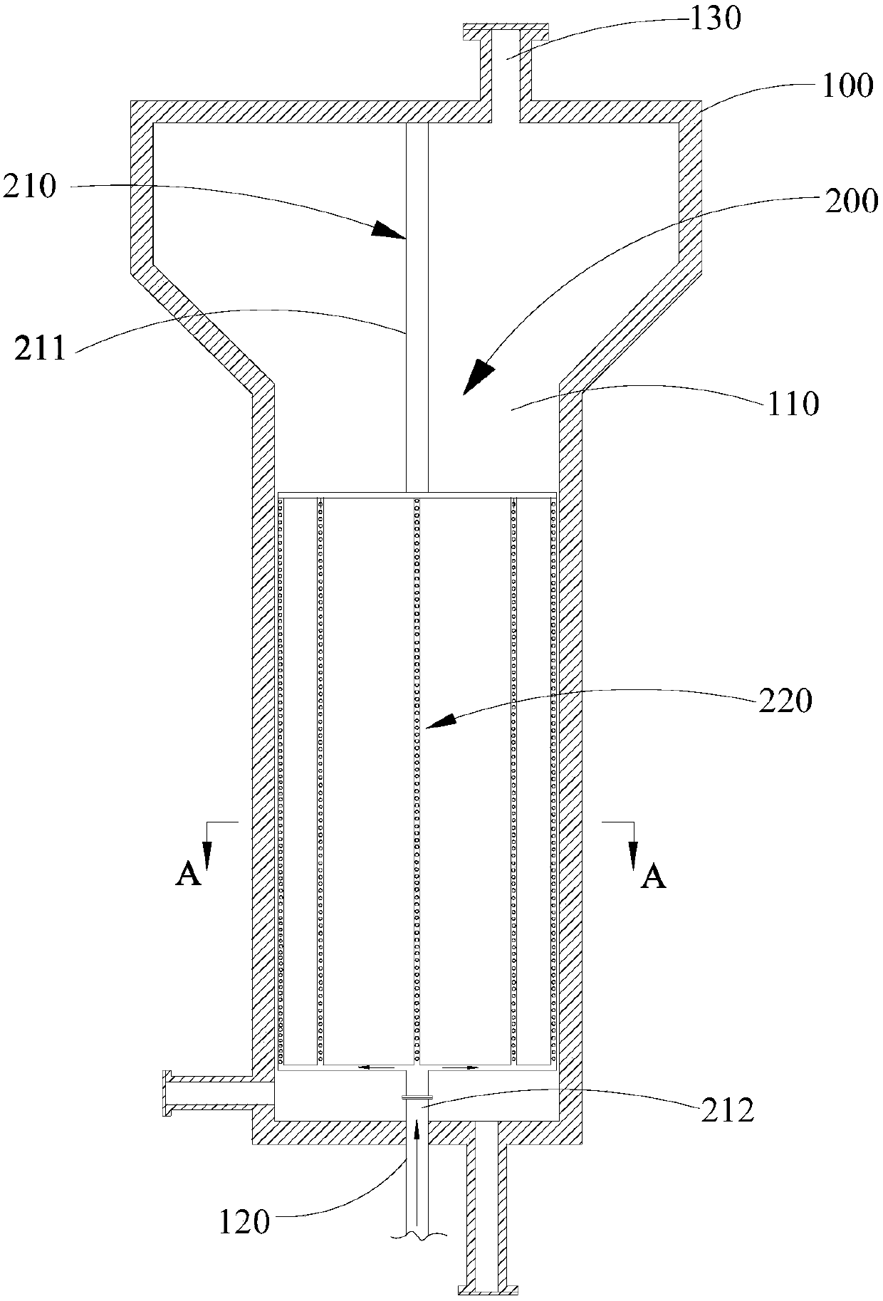
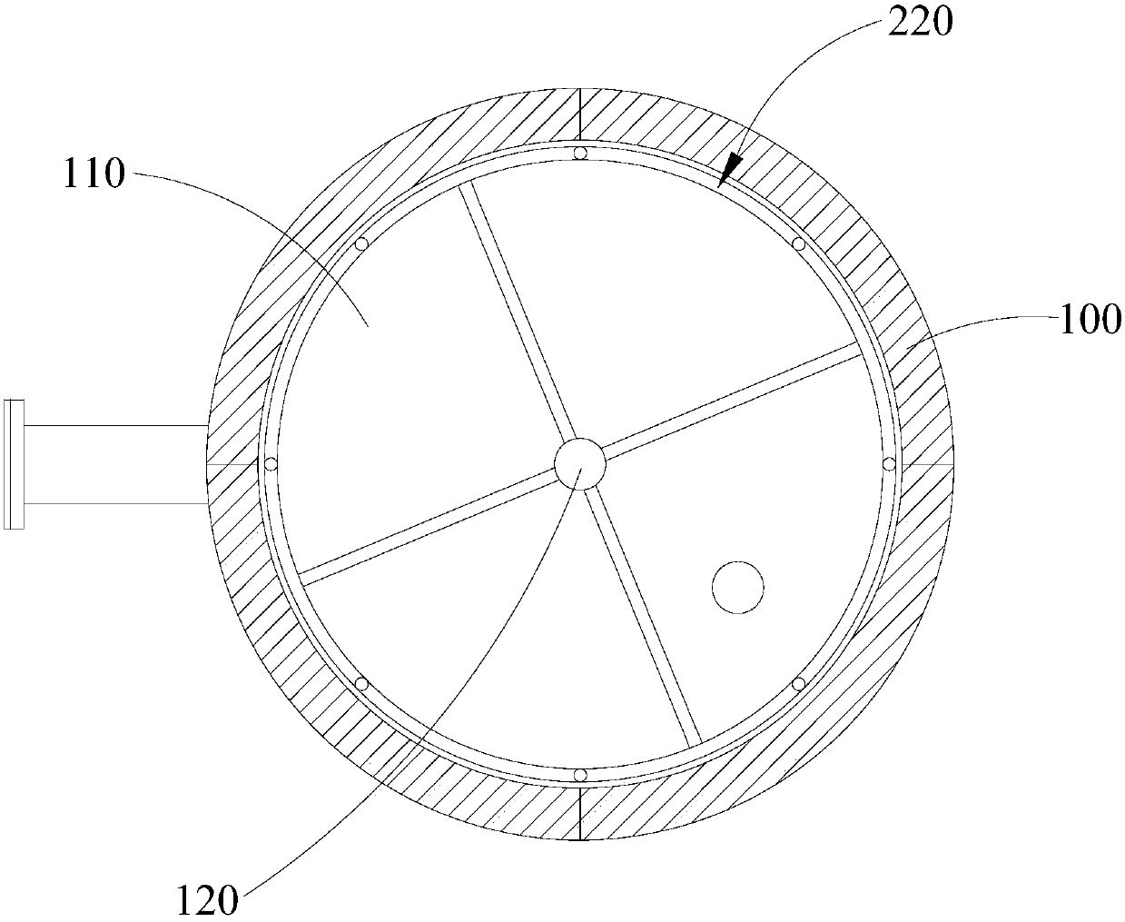
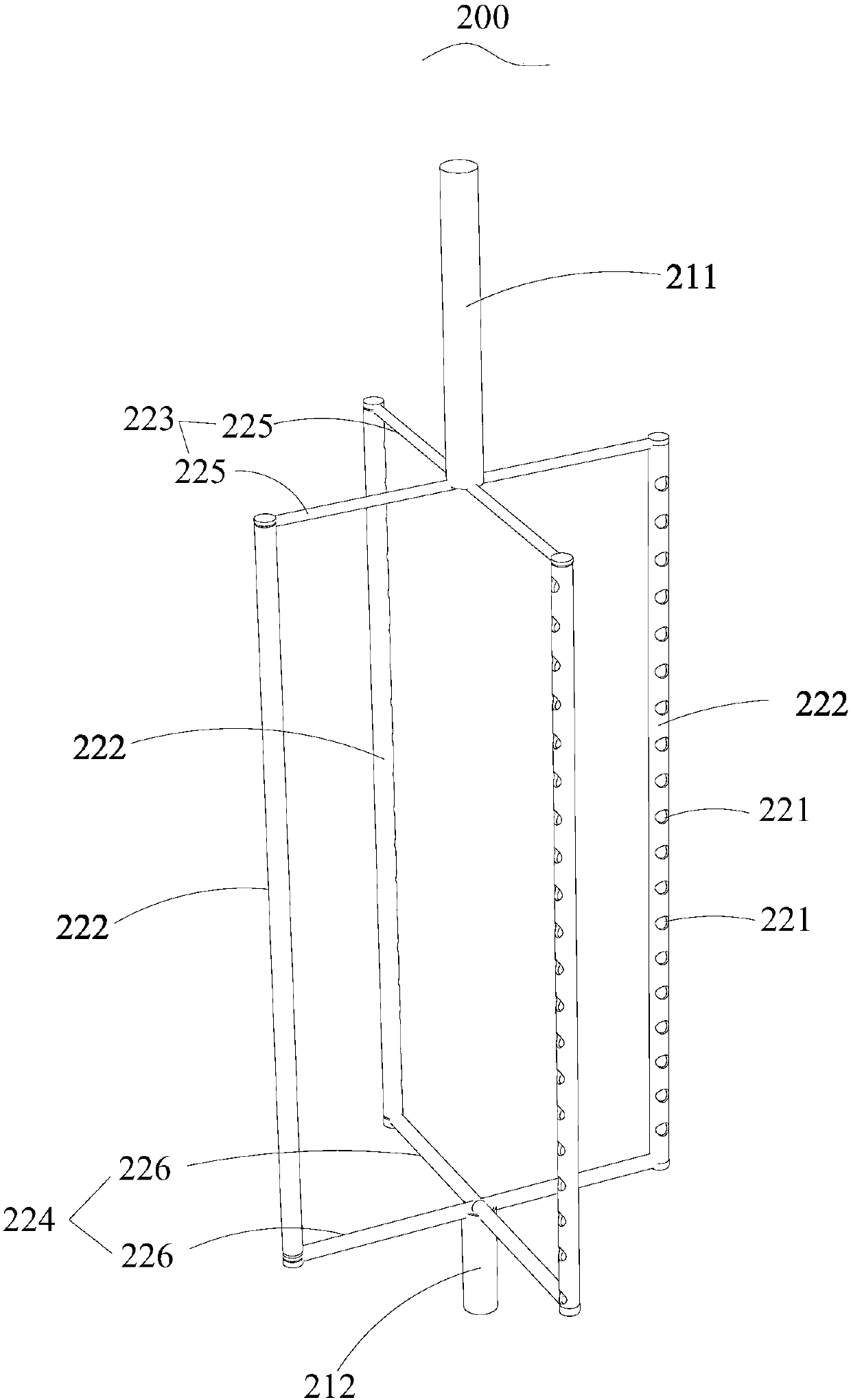
[0033] refer to figure 1 , figure 2 The self-cleaning fluidized bed reactor for carbon nanotube production provided by Embodiment 1 of the present invention includes a fluidized bed reactor body 100 having a reaction chamber 100 and a rotating device 200 disposed in the reaction chamber 100 . The rotating device 200 includes a rotating shaft 210 longitudinally arranged along the center of the reaction chamber 100 and a rotating body 220 connected to the rotating shaft 210 and capable of rotating driven by the rotating shaft 210 . The bottom of the reaction chamber 100 is provided with an inflow port 120 for the gas to flow in, and the top of the reaction chamber 100 is provided with an outflow port 130 for the gas to flow out. The rotating shaft 210 communicates with the inlet 120 , the rotating body 220 communicates with the rotating shaft 210 , and the rotating body 220 is provided with a plurality of air holes 221 facing the inner wall of the reaction chamber 100 and comm...

Embodiment 2

[0045] refer to Image 6 The self-cleaning fluidized bed reactor for carbon nanotube production provided by Embodiment 2 of the present invention differs from Embodiment 1 in that the structure of the rotating body 220 is different. In this embodiment, the rotating rod 222 in the rotating body 220 is curved. This curve design increases the number of air holes 221 per unit length at the same height of the rotating body 220 , the distribution of gas flowing out of the air holes 221 is more uniform, and the flushing efficiency of the gas is higher.

[0046] In addition, the structure of the upper connecting rod assembly 223 and the structure of the lower connecting rod assembly 224 are also different from the first embodiment. In this embodiment, the upper connecting rod assembly 223 includes a circular first upper connecting rod 2231 and two straight second upper connecting rods 2232. The upper ends of the four rotating rods 222 are connected to the first upper connecting rods....


PUM


Abstract

The invention relates to the technical field of a nanometer material and provides a self-cleaning fluidized bed reactor for carbon nanotube production. The self-cleaning fluidized bed reactor comprises a fluidized bed reactor body with a reaction chamber and a rotating device arranged in the reaction chamber, wherein the rotating device comprises a rotating shaft and a rotator; the rotating shaft is longitudinally arranged along the center of the reaction chamber; the rotator is connected with the rotating shaft and is rotated under the driving of the rotating shaft; the reaction chamber is provided with a flow inlet and a flow outlet; the gas flows in through the flow inlet and flows out through the flow outlet; the rotating shaft is communicated with the flow inlet; the rotator is communicated with the rotating shaft; a plurality of gas holes are formed on the rotator; the gas holes are opposite to the inner wall of the reaction chamber and are communicated with the rotating shaft; gas flows out through the gas holes. In the self-cleaning fluidized bed reactor for carbon nanotube production, the rotator is rotated under the driving of the back-flushing acting force of the gas flow; when the rotator is rotated, the catalyst and the carbon nanotube adhered to the inner wall of the reaction chamber are cleaned by the rotator; the inner wall of the reaction chamber is washed by the gas sprayed from the gas holes; the carbon nanotube is prevented from being locally accumulated on the inner wall of the reaction chamber and accordingly causing the reduction of effective volume in the fluidized bed.

Description

technical field [0001] The invention relates to the technical field of nanometer materials, and more specifically relates to a self-cleaning fluidized bed reactor for producing carbon nanotubes. Background technique [0002] As an emerging one-dimensional nanomaterial with excellent properties, carbon nanotubes are widely used in various aspects such as conductive media, composite materials, field emission, and energy storage materials for secondary lithium-ion batteries. The fluidized bed reactor is used in the large-scale production of carbon nanotubes. Its excellent heat transfer and mass transfer process make the catalyst fully contact with the raw material gas, and the reaction can obtain carbon nanotubes with excellent performance. [0003] Since carbon nanotubes are one-dimensional nanomaterials with a hollow structure, and have the characteristics of low volume density, large specific surface area, and high aspect ratio, carbon nanotubes are easily entangled with eac...

Claims


Application Information

Patent Timeline
Patent Type & Authority Patents(China)
IPC IPC(8): B01J8/24C01B32/16
CPCB01J8/008B01J8/24
Inventor 陈杰
Owner SHENZHEN SSZK NEW MATERIALS CO LTD
Why Eureka
Try Eureka