Pneumatic self-locking clamping fixture

A self-locking clamping and clamping technology, which is applied in the direction of clamping, manufacturing tools, metal processing machinery parts, etc., can solve the problems that affect the normal processing quality of the processed parts, cannot guarantee the accurate positioning of the processed parts, and the clamping position is unstable. , to achieve the effect of convenient and fast disassembly, precise positioning, and improved loading and unloading efficiency

Active Publication Date: 2019-03-12
杭州杭城摩擦材料有限公司
View PDF10 Cites 0 Cited by
  • Summary
  • Abstract
  • Description
  • Claims
  • Application Information

AI Technical Summary

Problems solved by technology

However, on the one hand, this utility model does not have a self-locking structure, and it is easy to cause unstable or misaligned clamping positions during the processing of complex parts or parts with large cutting forces, which greatly affects the normal processing and processing quality of the processed parts, and is also easy to On the other hand, the utility model is not provided with a positioning mandrel and a diamond-shaped positioning pin on the positioning element, so the positioning accuracy of the processed parts cannot be guaranteed, and the above-mentioned technical defects also exist

Method used


Image

  • Pneumatic self-locking clamping fixture
  • Pneumatic self-locking clamping fixture
  • Pneumatic self-locking clamping fixture

Examples


Embodiment 1

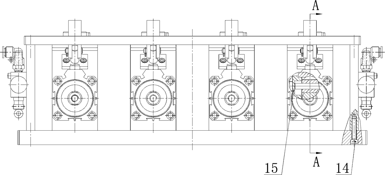
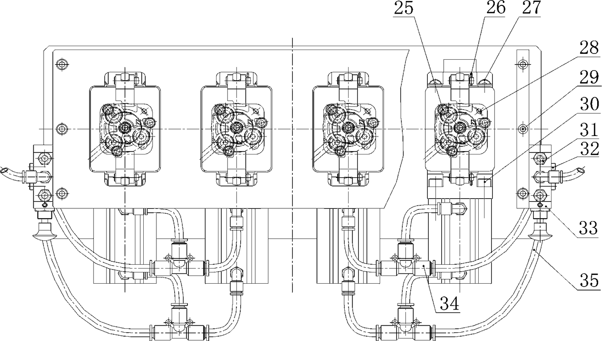
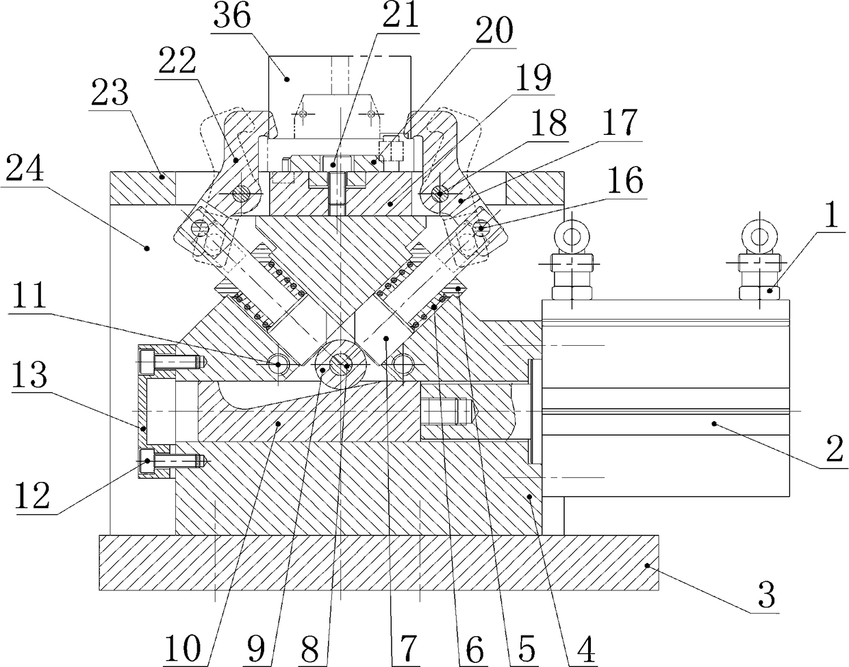
[0039] Such as Figure 1-3 As shown, the pneumatic self-locking clamping fixture includes a clamping device, and the clamping device adopts a wedge clamping mechanism, and the wedge clamping mechanism includes a wedge column 10 and a roller 9, and one end of the wedge column 10 is provided with There is a piston rod mounting stud, and a roller 9 is arranged on the working slope of the wedge column 10. The working slope is the contact surface of the clamping stroke between the wedge column 10 and the roller 9, and the self-locking angle of the clamping stroke Set to 5 degrees, the wedge clamping mechanism includes a power element, the power element adopts a cylinder, the cylinder adopts a double-acting cylinder, and the double-acting cylinder adopts a thin cylinder 2, and the thin cylinder 2 includes a piston rod. One end of the piston rod is provided with an internal thread interface, and the internal thread interface forms a fastening connection with the piston rod mounting s...

Embodiment 2

[0048] The pneumatic self-locking clamping fixture is similar to Embodiment 1, except that the self-locking angle of the clamping stroke is set to 10 degrees.

Embodiment 3

[0050] The pneumatic self-locking clamping fixture is similar to Embodiment 1, except that the self-locking angle of the clamping stroke is set to 15 degrees.


PUM


Abstract

The invention relates to a pneumatic self-locking clamping fixture. The fixture comprises a clamping device, wherein the clamping device adopts a wedge clamping mechanism, the wedge clamping mechanism comprises a wedge column (10) and a roller (9), a piston rod mounting double-screw bolt is arranged at one end of the wedge column (10), and the roller (9) is arranged on an inclined working surface of the wedge column (10). Compared with the prior art, the fixture has the beneficial effects as follows: clamping self-locking is controlled by the aid of a double-acting air cylinder, convenient and quick mounting and dismounting are realized, automatic and synchronous clamping is realized by the aid of a double-pressing-plate clamping structure, and the fixture can clamp a to-be-machined part firmly and realize quick self-locking in an instant and can also release the to-be-machined part in an instant after machining is completed, so that the mounting and dismounting efficiency is substantially improved; two guiding columns are arranged to form a cross structure, and thus relatively small workpieces can be clamped to be machined; the fixture has an oblong appearance, and multiple machining stations can be arranged according to sizes of workpieces, accordingly, the multiple workpieces can be machined simultaneously, the machining cost is saved, and the economic benefit is substantially increased.

Description

technical field [0001] The invention relates to a machine tool fixture, in particular to a pneumatic self-locking clamping fixture. Background technique [0002] The Chinese utility model patent No. ZL201520485952.7 discloses a double-platen fixture, which includes a platen, a remote rod, a cylinder, a thrust rod, a clamp body, a supporting plate and a piston rod. The fixture is provided with two pressure plates, and the pressure plate is supported by two rockers of equal length, forming a parallelogram mechanism with the clamp body; two piston rods are installed at both ends of the cylinder, and the piston rod is connected to the pressure plate. The cylinder is connected with the clamp body through a thrust rod. When the piston rod of the cylinder moves up and down, the pressure plate will always be parallel to the horizontal base surface of the clamp body to complete the forward-tightening-loosen-backward action, which can be adjusted according to the workpiece. Shape, th...

Claims


Application Information

Patent Timeline
Patent Type & Authority Patents(China)
IPC IPC(8): B23Q3/08
CPCB23Q3/061B23Q3/08
Inventor 陈建余永洪唐光林唐春艳
Owner 杭州杭城摩擦材料有限公司
Why Eureka
Try Eureka