
Three-dimensional deep composite sand control method for oil and gas wells

A three-dimensional technology for oil and gas wells, applied in the direction of production fluid, earthwork drilling, wellbore/well components, etc., can solve the problems of reducing the effective period of sand control, erosion of sand control pipes, serious reservoir damage, etc., and overcome the problem of drilling plugs in the wellbore , extend the service life, expand the effect of the affected volume

Inactive Publication Date: 2019-04-16
CHONGQING UNIVERSITY OF SCIENCE AND TECHNOLOGY
View PDF6 Cites 0 Cited by
  • Summary
  • Abstract
  • Description
  • Claims
  • Application Information

AI Technical Summary

Problems solved by technology

However, mechanical sand control does not block the large pores with high permeability and high permeability formed inside the reservoir, and cannot solve complex problems such as water channeling, steam channeling, and water content rise; it does not consolidate the loose sand particles inside the reservoir , it is easy to cause erosion of the sand control pipe and reduce the effective period of sand control
The disadvantage of chemical sand control is that the injection agent has aging phenomenon and the validity period is short; the damage to the reservoir is serious, and the production of oil and gas wells decreases after sand control

Method used


Image

  • Three-dimensional deep composite sand control method for oil and gas wells
  • Three-dimensional deep composite sand control method for oil and gas wells
  • Three-dimensional deep composite sand control method for oil and gas wells

Examples


Embodiment Construction

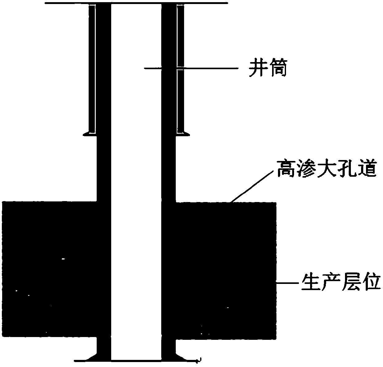
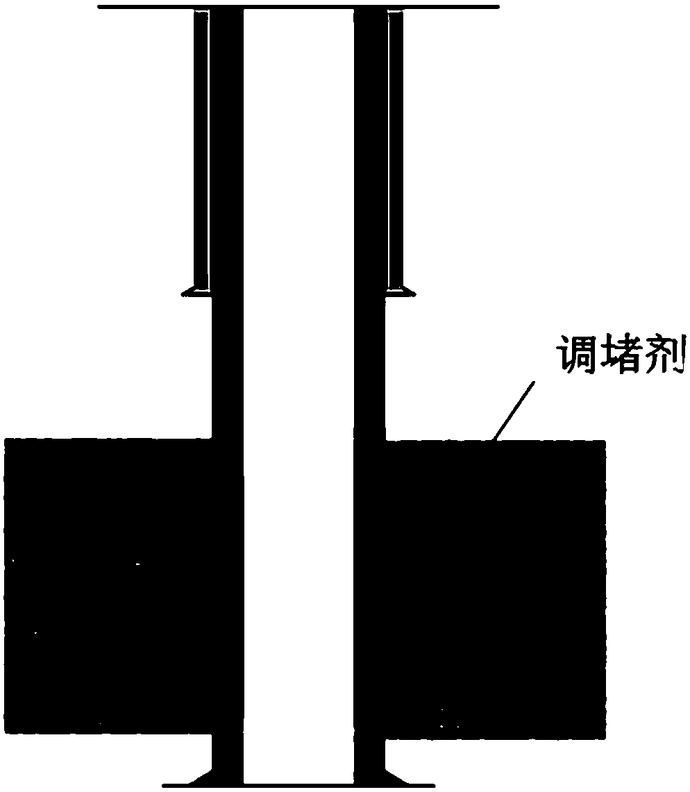
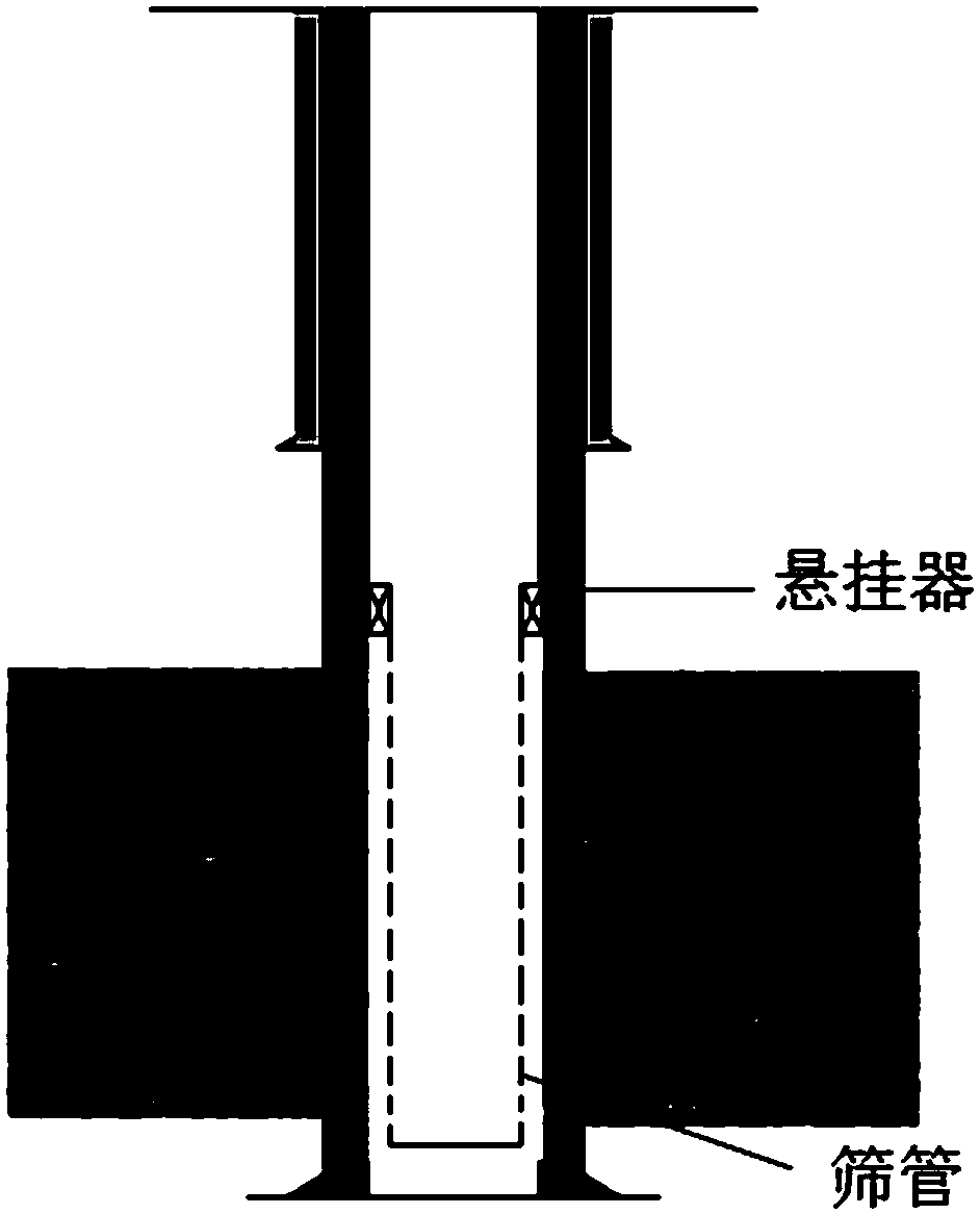
[0020] The three-dimensional deep composite sand control method for oil and gas wells comprises the following steps,

[0021] Step 1: Before construction, take on-site water samples for formula optimization and screening to determine the best formula of plugging agent; determine the treatment radius according to the sand and water output conditions, and calculate the dosage of plugging agent;

[0022] Step 2: Test the water absorption index of the target well to understand the suction capacity of the well, determine the construction pressure range and displacement according to the pressure stability, and improve the efficiency of the plugging agent entering the plugging zone;

[0023] Step 3: Determine the squeeze injection method of the plugging agent, and the squeeze injection pressure shall not exceed 80% of the fracture pressure of the formation; Drilling, retrievable bridge plugs or sand filling are used to protect non-operating formations; for thin formations or conditio...


PUM


Abstract

The invention relates to a three-dimensional deep-formation compound sand control method for an oil and gas well under complex conditions of sand production and accompanying of water channeling, gas channeling or water cut increasing and the like. The method comprises the following steps: determining an optimal formula of a profile control agent; calculating the use quantity of the profile control agent; testing a water injective index of a target well, knowing about the injection capacity of the well, determining the construction pressure range and displacement based on the pressure stability condition, and increasing the effective rate of plugging zone entry by the profile control agent; determining the squeezing manner of the profile control agent, wherein the squeezing pressure is lower than 80% of the formation fracturing pressure; descending a construction pipe string, connecting with a ground pipeline, preparing the profile control agent, and starting a pump truck set to squeeze the profile control agent after sufficient stirring; after squeezing is completed, continuing to inject clear water for over displacement, performing over-displacement on a plugging agent in a shaft, ejecting the plugging agent into a producing formation by certain depth, and guaranteeing that the plugging agent is 3-5 meters away from a well hole; shutting in the well and waiting on cement setting for 24-48 hours; descending a precise microporous compound sand control sieve pipe string, and performing well completion after completing hanging and sealing of sieve pipes.

Description

technical field [0001] The invention relates to a method for downhole operation of oil and gas exploitation, in particular to a three-dimensional deep layer composite sand control method for oil and gas wells under complex conditions such as sand production in oil and gas wells accompanied by water channeling, gas channeling or water content rise. Background technique [0002] Unconsolidated sandstone oil and gas reservoirs have low rock particle cementation strength and are prone to sand production during oil and gas well production, which has many adverse effects on oil and gas field production management. Especially for unconsolidated sandstone oil and gas reservoirs developed by water injection and steam injection, the injection of water and steam can easily reduce the strength of reservoir rocks and intensify the sand production of oil and gas wells. At the same time, due to the long-term sand production of oil and gas wells and the injection of foreign fluids, it is ea...

Claims


Application Information

Patent Timeline
Patent Type & Authority Patents(China)
IPC IPC(8): E21B33/138E21B43/08
CPCE21B33/138E21B43/08
Inventor 徐家年刘虹利王郑库李凤霞张振军史海涛黄显德
Owner CHONGQING UNIVERSITY OF SCIENCE AND TECHNOLOGY
Learn More