Filter tank adopting work-condition-adaptive filtering, magnetization, rotary magnetic field and centrifugation

An adaptive filtering and rotating magnetic field technology, applied in fluid pressure actuating devices, fluid pressure actuating system components, mechanical equipment, etc., to solve problems such as different cleanliness requirements, reduced filter element service life, and reduced filter speed. , to reduce the cost and complexity of filtering, suppress the increase in the thickness of the filter cake, and improve the filtering performance.

Inactive Publication Date: 2016-08-17
谢阿招
View PDF6 Cites 0 Cited by
  • Summary
  • Abstract
  • Description
  • Claims
  • Application Information

AI Technical Summary

Problems solved by technology

[0004] However, the high-pressure filter used in the existing hydraulic system has the following deficiencies: (1) various hydraulic components have different requirements for the cleanliness of the oil, and the particle sizes of the solid particles in the oil are also different. This requires the installation of many different types of filters at different positions in the hydraulic system, which brings about problems of cost and installation complexity; (2) The filter in the hydraulic system mainly adopts the filter cake filter method, and the filtrate is perpendicular to the The surface of the filter element flows, and the intercepted solid particles form a filter cake and gradually thicken, and the filtration speed gradually decreases until the filtrate stops flowing out, which reduces the service life of the filter element

Method used


Image

  • Filter tank adopting work-condition-adaptive filtering, magnetization, rotary magnetic field and centrifugation
  • Filter tank adopting work-condition-adaptive filtering, magnetization, rotary magnetic field and centrifugation
  • Filter tank adopting work-condition-adaptive filtering, magnetization, rotary magnetic field and centrifugation

Examples


Embodiment Construction

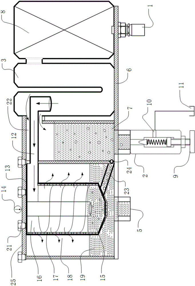
[0040] Please refer to the attached figure 1 to attach Figure 19 As shown, the present invention is a kind of filtering box with working condition self-adaptive filtering, magnetization, rotating magnetic field and centrifugal, and it is made up of bottom plate 6, filter 8, U-shaped particulate separation module 3, oil return cylinder 7, inner cylinder 15, Several parts such as spiral channel 17, filter element 18, outer tub 19 and end cap 25 are formed. Wherein, the filter 8 , the U-shaped particulate separation module 2 , the oil return cylinder 7 , and the outer barrel 19 are placed on the bottom plate 6 in sequence.

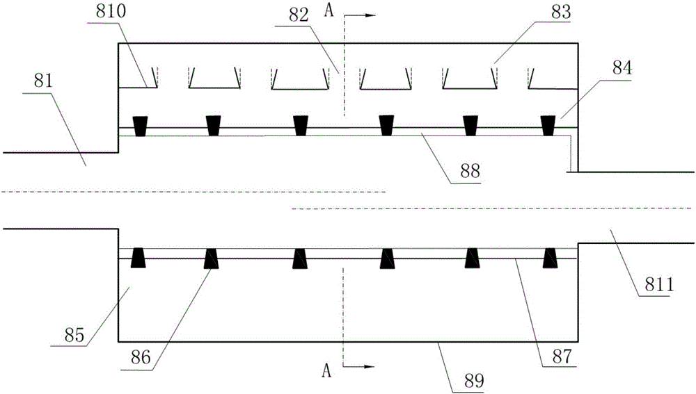
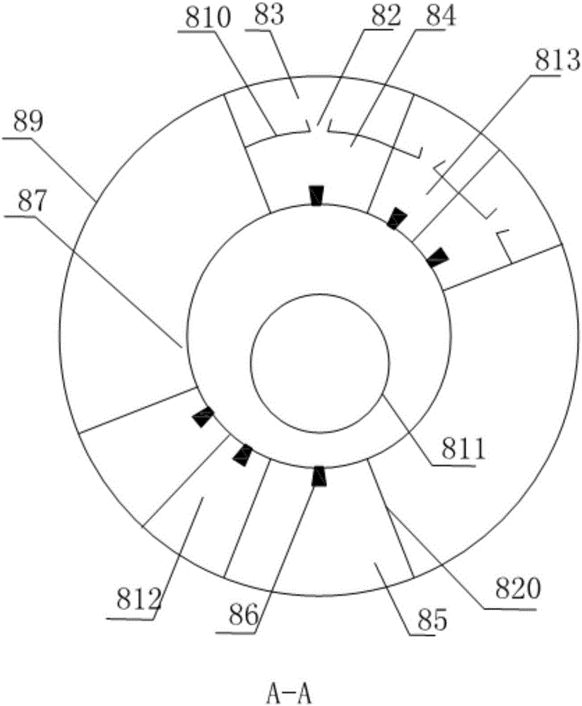
[0041] The filter 8 is used to input the hydraulic oil, and can attenuate the pulsating pressure in the high, medium and low frequency bands in the hydraulic system, and suppress the flow fluctuation. The filter 8 is composed of an input tube 81 , a housing 89 , an output tube 811 , an elastic thin wall 87 , a plug-in H-type filter 812 and a plug-in series...


PUM


Abstract

The invention relates to a filter box with working condition adaptive filtering, magnetization, rotating magnetic field and centrifugal. The filter, U-shaped particle separation module, oil return cylinder and outer barrel are placed on the bottom plate in sequence; the filter and U-shaped particle The separation module is connected, which adopts a working condition adaptive filter; the U-shaped particle separation module includes a U-shaped tube, and the U-shaped tube is sequentially installed with a temperature control module, a magnetization module, a mechanical centrifuge module, a first adsorption module, and a rotating magnetic field centrifuge. module, the second adsorption module and the degaussing module; the U-shaped particle separation module and the upper part of the oil return cylinder are connected through the oil return pipe of the oil return cylinder; the inner cylinder is placed in the outer barrel, which is installed on the end cover; the spiral flow channel is contained in the In the barrel, it is connected with the U-shaped particle separation module through the oil inlet pipe of the inner barrel; the oil inlet pipe of the inner barrel is located in the oil inlet pipe of the oil return barrel; the filter element is arranged on the inner wall of the inner barrel. The invention has many advantages such as good filtering performance, high adaptability and integration, long service life and the like.

Description

【Technical field】 [0001] The invention relates to a hydraulic oil filter box, in particular to a filter box using working condition self-adaptive filtering, magnetization, rotating magnetic field and centrifugal, and belongs to the technical field of hydraulic equipment. 【Background technique】 [0002] Statistics at home and abroad show that about 70% to 85% of hydraulic system failures are caused by oil pollution. Solid particles are the most common and harmful pollutants in oil pollution. Hydraulic system failures caused by solid particle pollutants account for 70% of total pollution failures. Metal debris accounts for 20% to 70% of the particle pollutants in hydraulic system oil. Taking effective measures to filter out the solid particle pollutants in the oil is the key to the pollution control of the hydraulic system, and it is also a reliable guarantee for the safe operation of the system. [0003] Filters are key components of hydraulic systems to remove solid parti...

Claims


Application Information

Patent Timeline
IPC IPC(8): F15B21/04
CPCF15B21/041
Inventor 谢阿招
Owner 谢阿招
Why Eureka
Try Eureka