Pipeline-used expansion joint with second-level pressurization structure

An expansion joint with its own technology, applied in the field of expansion joints, can solve the problems of large internal and external pressure difference, property loss, short fatigue life, etc., and achieve the effect of improving the use pressure occasion, meeting the demand of high-pressure pipelines, and meeting the requirements of temperature compensation

Active Publication Date: 2016-08-17
LUOYANG SUNRUI SPECIAL EQUIP
View PDF6 Cites 2 Cited by
  • Summary
  • Abstract
  • Description
  • Claims
  • Application Information

AI Technical Summary

Problems solved by technology

The compensator selected for the existing pipeline only bears internal pressure or external pressure, the internal and external pressure difference is large, the bellows is in a state of high stress, and the fatigue life is short
At the same time, due to the lack of an alarm device, it is not easy to find out in time after the bellows breaks, resulting in the leakage of the pipeline medium, resulting in property loss and safety accidents.

Method used


Image

  • Pipeline-used expansion joint with second-level pressurization structure
  • Pipeline-used expansion joint with second-level pressurization structure
  • Pipeline-used expansion joint with second-level pressurization structure

Examples


Embodiment 1

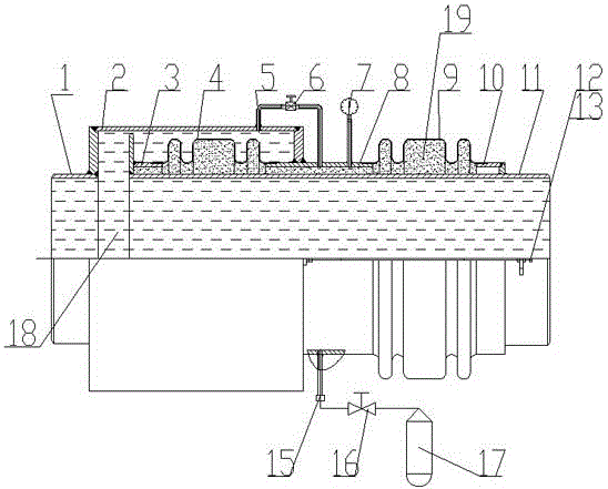
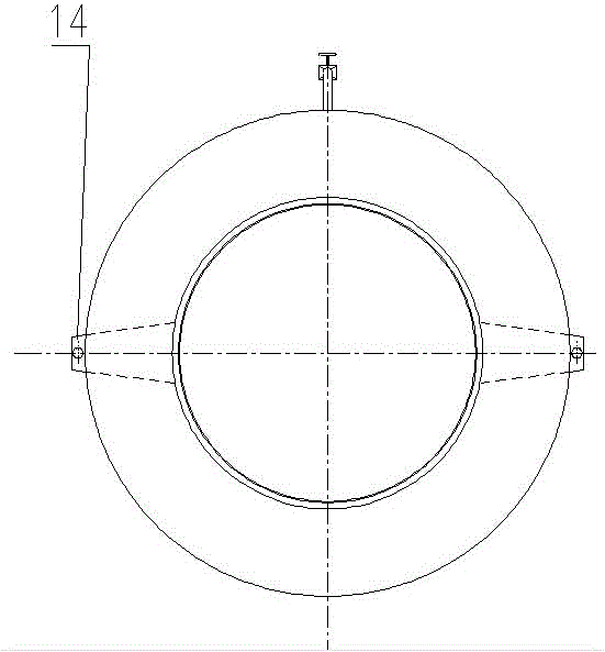
[0023] Such as figure 1 and figure 2 The pipeline expansion joint with self-contained secondary pressure shown in the figure is an external pressure type, and the waveform parameters and wave numbers of the working bellows 4 and the protection bellows 9 are the same. The inlet pipe assembly 1, the outer pipe 2, the middle pipe assembly 8, the working bellows 4, the inner end ring assembly 3, and the outlet pipe 11 form a fluid medium space, and the working bellows bear the high external pressure of the working fluid medium. The protection bellows 9 is welded with the outer end ring assembly 10 to form a secondary pressurization chamber, the working bellows bears the internal pressure set by the pressurization medium, and the protection bellows also bears the internal pressure of the pressurization medium. In this way, the pressure difference between the inner and outer surfaces of the working bellows will be reduced, and the stress situation will be greatly improved, which i...

Embodiment 2

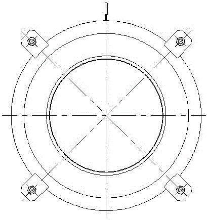
[0026] Such as image 3 and Figure 4 As shown, the pipeline expansion joint adopts the internal pressure type, the inlet pipe assembly 1, the working bellows 4, and the outlet pipe 11 form a fluid medium space, and the working bellows bears the high internal pressure of the working fluid medium. The protection bellows 9 is welded with the outer pipe 2 to form a secondary pressurization chamber, the working bellows bears the external pressure set by the pressurization medium, and the protection bellows bears the internal pressure of the pressurization medium. In this way, the pressure difference between the inner and outer surfaces of the working bellows will be reduced, and the stress situation will be greatly improved, which is beneficial to improving the service life of the working bellows.

[0027] The pressurized medium 19 is gas, which is filled by the external pressurized gas cylinder 17 through the pressurized valve 16 and the plugging pipe 15 . The pressure chamber ...


PUM


Abstract

The invention relates to a pipeline-used expansion joint with a second-level pressurization structure. The pipeline-used expansion joint comprises a working corrugated pipe used for compensating expansion and contraction of a pipeline; the working corrugated pipe is connected to the pipeline and bears the internal pressure applied by a fluid medium inside the pipeline to the inner wall of the working corrugated pipe, or the working corrugated pipe is arranged inside the pipeline and bears the external pressure applied by the fluid medium inside the pipeline to the outer wall of the working corrugated pipe; the outside or the inside of the working corrugated pipe is provided with a pressurization medium used for applying the pressure opposite to the pressure of the fluid medium to the working corrugated pipe; and the pressurization medium communicates into a protective corrugated pipe. By means of the pipeline-used expansion joint with the second-level pressurization and alarm structure, the working stress state of each corrugated pipe can be lowered; the temperature compensation requirement of the pipeline is met; the service life of each corrugated pipe is prolonged; and the requirement of safe use is met.

Description

technical field [0001] The invention relates to an expansion joint, in particular to an expansion joint for a pipeline with its own secondary pressure charging. Background technique [0002] With the advancement of urbanization and industrialization in my country, centralized heating projects and petrochemical projects are being constructed on a large scale, and there are temperature changes in the pipelines that transport fluid media. The pipelines need to be designed with compensator expansion joints to compensate for the thermal expansion and contraction of the pipelines, so as to reduce the temperature of the pipelines. Stress, to ensure the safe operation of the pipeline system. The compensator selected for the existing pipeline only bears internal pressure or external pressure, the internal and external pressure difference is relatively large, the bellows is in a state of high stress, and the fatigue life is short. At the same time, due to the lack of an alarm device, ...

Claims


Application Information

Patent Timeline
Patent Type & Authority Applications(China)
IPC IPC(8): F16L51/03
CPCF16L51/03
Inventor 郑大远李凯李世乾王伟兵张爱琴杨萌
Owner LUOYANG SUNRUI SPECIAL EQUIP
Why Eureka
Try Eureka