Method for adjusting negative temperature coefficients of constant current source and constant current source

A technology with negative temperature coefficient and constant current source, which is applied in the field of constant current source, can solve the problems of increased circuit volume, inability to integrate, expensive thermistor, etc., achieve small size, easy integration, and improve the effect of low temperature start-up difficulty

Active Publication Date: 2013-06-05
MORNSUN GUANGZHOU SCI & TECH
View PDF7 Cites 6 Cited by
  • Summary
  • Abstract
  • Description
  • Claims
  • Application Information

AI Technical Summary

Problems solved by technology

However, the thermistor is more expensive and cannot be integrated, which will increase the circuit size

Method used


Image

  • Method for adjusting negative temperature coefficients of constant current source and constant current source
  • Method for adjusting negative temperature coefficients of constant current source and constant current source
  • Method for adjusting negative temperature coefficients of constant current source and constant current source

Examples


Embodiment 1

[0033] Such as image 3 Shown is Embodiment 1 of the method for adjusting the negative temperature coefficient of the constant current source of the present invention. This embodiment proposes a method for increasing the negative temperature coefficient with strong applicability and applicability.

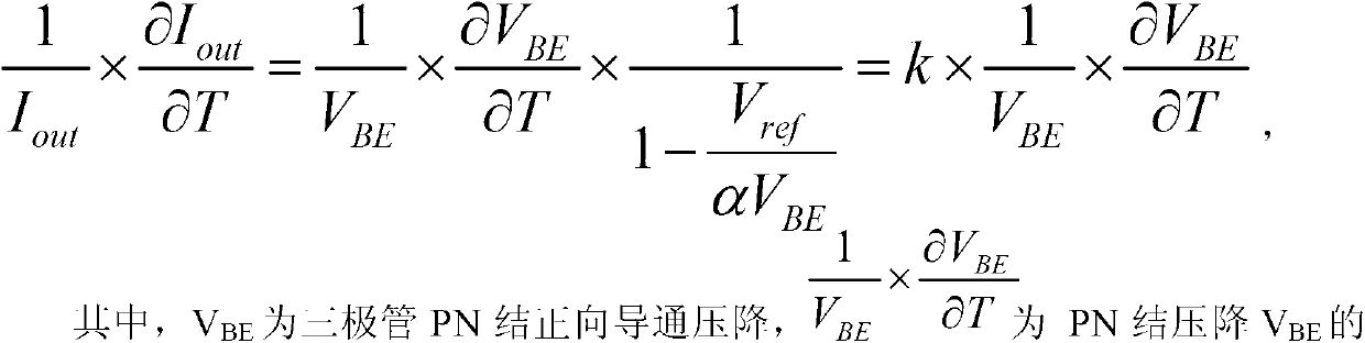
[0034] Through the calculation of voltage, set the voltage relationship as V=αV BE -V ref Then use the operational amplifier and NMOS tube to form a transconductance amplifier. The input voltage is used as the input voltage of the transconductance amplifier. The input voltage is added to the resistor R0 to convert it into a current, which is used as the output current of the constant current source. Because the current consumed by the circuit that generates the voltage relation in the integrated circuit can be made very small (microampere level), such a small current can be ignored compared to the constant current source used in general. Then by selecting the value of the set con...

Embodiment 2

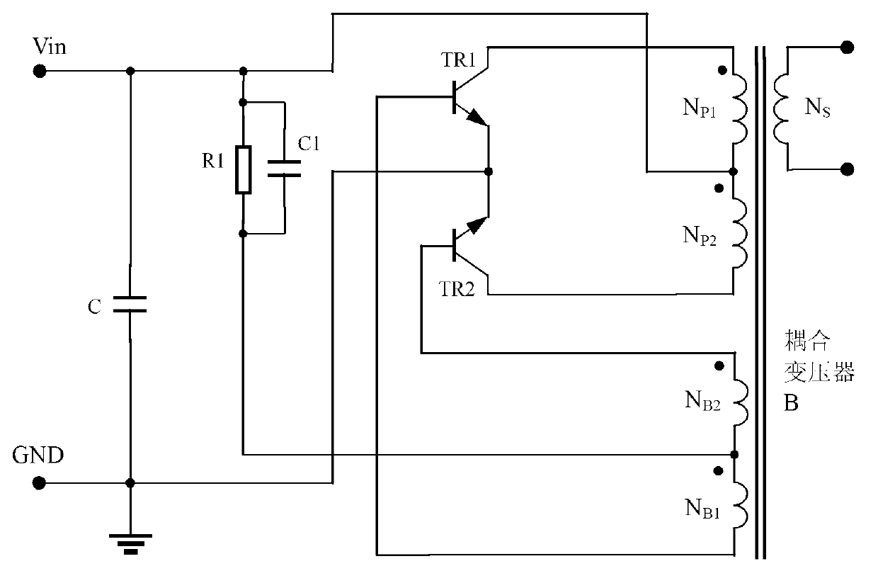
[0039] Such as Figure 4 The shown constant current source includes a power supply terminal VCC, a first resistor R11, a second resistor R10, a first transistor Q10, a second transistor Q11, a third transistor Q12 and a fourth transistor Q13, the resistance value of the first resistor R11 is much larger than the resistance value of the second resistor R10, the larger the resistance value of the first resistor R11, the better, and the ideal value is infinite, so that the constant current value of this constant current source is closer to the value passed through the second resistor The current value of a resistor R10; one end of the first resistor R11 is connected to the power supply terminal VCC, and the other end of the first resistor R11 is respectively connected to the collector of the first triode Q10, the collector of the second triode Q11 and the fourth triode The base of the transistor Q13 is connected, the emitter of the fourth transistor Q13 is respectively connected ...

Embodiment 3

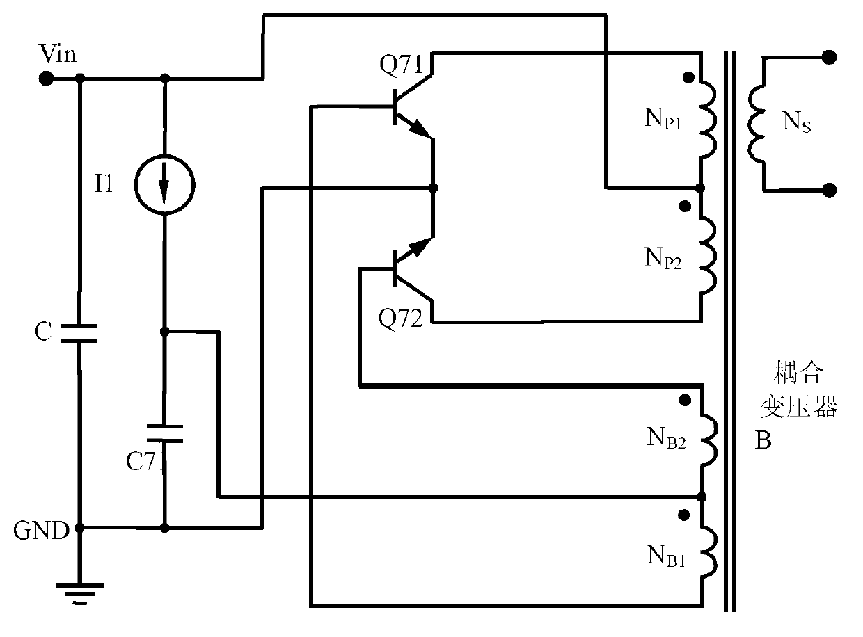
[0056] Such as Figure 7 Shown is the second embodiment of the constant current source of the present invention. The difference between the second embodiment and the first embodiment is that a fifth triode Q14 is added. The other end of the first resistor R11 is connected to the base of the fifth transistor Q14, the collector of the fifth transistor Q14 is connected to the power supply terminal VCC, and the emitter of the fifth transistor Q14 is connected to the fourth transistor Q13. connected to the base of the fourth transistor Q13 so as to form a composite tube through the fifth transistor Q14 and the fourth transistor Q13, so as to improve the driving capability of the base of the fourth transistor Q13, so that the resistance value of the first resistor R11 can be further improved Increase.


PUM


Abstract

The invention discloses a method for adjusting negative temperature coefficients of constant current source. The method for adjusting the negative temperature coefficients of the constant current source includes that input voltage V = alpha V BE - V ref is set; the input voltage is added to a resistor to convert to output current I out of the constant current source to obtain a temperature coefficient of the constant current source, wherein V BE is PN junction forward conduction voltage drop of a triode, 1 / V BE * alpha V BE / alpha T is a negative temperature coefficient of the PN junction voltage drop VBE, alpha is a constant, V ref is reference voltage, and T is a temperature; and values of the constant alpha and or values of the reference voltage V ref are selected and set to enable the constant current source to obtain k times negative temperature coefficient of PN junction of the triode to achieve adjustment of the negative temperature coefficients of the constant current source. The invention discloses the constant current source utilizing the method for adjusting the negative temperature coefficients of the constant current source as well. The method for adjusting the negative temperature coefficients of the constant current source and the constant current source utilizing the same have the advantage of being capable of conveniently and greatly adjusting to obtain the negative temperature coefficients of the constant current source.

Description

technical field [0001] The invention relates to a constant current source, in particular to a method for adjusting the negative temperature coefficient of the constant current source, and also relates to a constant current source using the method. Background technique [0002] The ideal constant current source is independent of voltage and temperature, that is, the internal resistance of the constant current source is infinite, and the current value does not change with temperature. Such as figure 1 The general traditional self-excited push-pull converter circuit shown, this kind of self-excited push-pull converter circuit has the disadvantages of being difficult to start at low temperature and easy to burn out in high temperature short circuit, because the self-excited push-pull converter circuit at low temperature The magnification of the circuit is small and requires a large starting current, but at high temperatures the magnification of the circuit is large and only req...

Claims


Application Information

Patent Timeline
IPC IPC(8): G05F1/56
Inventor 唐盛斌
Owner MORNSUN GUANGZHOU SCI & TECH
Why Eureka
Try Eureka