Load control circuit and its control method

A control method and load control technology, applied in the direction of program control, computer control, general control system, etc., can solve problems such as accidents and controller interference

Active Publication Date: 2018-08-10
GUANGZHOU LIANTE ELECTRONICS TECH CO LTD
View PDF8 Cites 0 Cited by
  • Summary
  • Abstract
  • Description
  • Claims
  • Application Information

AI Technical Summary

Problems solved by technology

[0004] The purpose of the present invention is to propose a load control circuit, which can solve the problem that the controller is disturbed and easily causes accidents

Method used


Image

  • Load control circuit and its control method
  • Load control circuit and its control method

Examples


Embodiment Construction

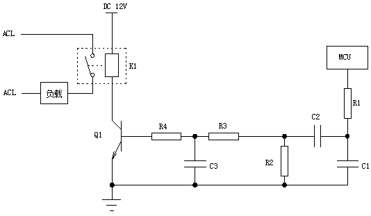
[0017] Below, in conjunction with accompanying drawing and specific embodiment, the present invention is described further:

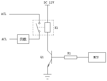
[0018] Such as figure 2 As shown, a load control circuit includes a low-pass filter, a high-pass filter, a drive circuit, an electronic switch and a relay circuit connected in sequence, and the low-pass filter and the high-pass filter are connected to form a band-pass filter; the low-pass The critical frequency of the filter is ω1, the critical frequency of the high-pass filter is ω2, and ω1>ω2. The low-pass filter is used to connect with the control signal output end of a controller; the band-pass filter is used to gate the control signal output by the control signal output end of the controller; the drive circuit uses Controlling the on and off of the electronic switch according to the control signal after gating processing, and then controlling the working state of the relay circuit; the relay circuit is used to control the connection and disconnec...


PUM


Abstract

The invention relates to a load control circuit and a control method thereof. The load control circuit comprises a low-pass filter, a high-pass filter, a driving circuit, an electronic switch and a relay circuit, wherein the low-pass filter, the high-pass filter, the driving circuit, the electronic switch and the relay circuit are successively connected. The low-pass filter is connected with the high-pass filter, thereby forming a band pass filter. The critical frequency of the low-pass filter is omega1, and the critical frequency of the high-pass filter is omega2, wherein omega1>omega2. The low-pass filter is used for connecting with the control signal output end of a controller. The band pass filter is used for performing gating processing on a control signal which is output from the control signal output end of the controller. The driving circuit is used for switching on and switching off the electronic switch according to the control signal after gating process and furthermore controlling the operation state of the relay circuit. The relay circuit is used for connecting and disconnecting a load and a power supply. The load control circuit and the control method thereof can settle a problem of easy accident caused by interference to the controller.

Description

technical field [0001] The invention relates to a load control circuit and a control method thereof. Background technique [0002] figure 1 It is a common load control circuit. The MCU gives a very high potential to the base of the transistor Q1, the collector and the emitter of the transistor Q1 are turned on, and the relay K1 controls the coil to form a path to close the load end. The MCU supplies a low potential to the base of the triode Q1, the collector and emitter of the triode Q1, and the control coil of the relay K1 are opened, the normally open contact of the relay K1 is disconnected, and the load stops working. The above controls are all initiated by the MCU. If the MCU is disturbed and fails, the base of the transistor Q1 is always at a high level, causing the load to work for a long time and cannot be turned off, causing a safety accident. For example, if the load is a high-power heating device, it will cause a fire. [0003] Nowadays, there are a lot of elec...

Claims


Application Information

Patent Timeline
Patent Type & Authority Patents(China)
IPC IPC(8): G05B19/042
CPCG05B19/042
Inventor 冷磊贺勇锋
Owner GUANGZHOU LIANTE ELECTRONICS TECH CO LTD
Why Eureka
Try Eureka