Automatic plugging-in device of connector pin

An automatic insertion and connector technology, applied in the assembly/disassembly of contacts, can solve the problems of non-adjustment, high noise, time-consuming and labor-intensive, etc., and achieve the effect of convenient feeding and improving production efficiency.

Active Publication Date: 2016-08-17
昆山市德来福工业自动化有限公司
View PDF5 Cites 12 Cited by
  • Summary
  • Abstract
  • Description
  • Claims
  • Application Information

AI Technical Summary

Problems solved by technology

In the prior art connector pin mounting equipment, there are roughly three driving methods: 1) cylinder type, which is slow, noisy, and complex in structure, and can only be applied to a small number of products; 2) servo motor type, although Its speed is fast, but its structure is complicated, and its product versatility is poor; 3) mechanical cam type, its speed is fast, but it cannot be adjusted, and its

Method used


Image

  • Automatic plugging-in device of connector pin
  • Automatic plugging-in device of connector pin
  • Automatic plugging-in device of connector pin

Examples


Embodiment

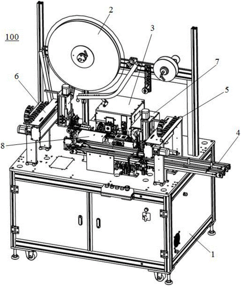
[0054] Please refer to Figure 1-Figure 19 , the present embodiment is an automatic insertion device 100 for connector pins, which includes a frame 1, a feeding device 2 fixed on the frame 1 for storing pin coils, and a plugging device 2 docked with the feeding device 2. Device 3, the terminal conveying device 4 arranged in front of the plug-in device 3, the feeding device 5 and the unloading device 6 arranged at both ends of the terminal conveying device 4, the CCD camera device 7 arranged on the side of the plug-in device 3, and the The terminal receiving device 8 between the plug-in device 3 and the terminal conveying device 4 .

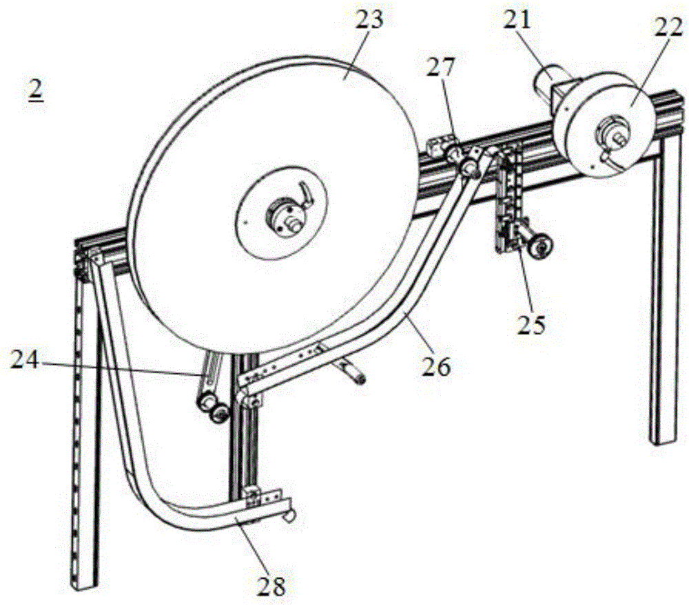
[0055] The discharge device 2 includes a first driving device 21 fixed on the frame 1 to provide power for the transmission of the material belt, a driving wheel 22 fixed on the rotating end of the first driving device 21, a discharging roller 23 for storing and discharging the material belt, The first tensioning device 24 on the edge of the mate...


PUM


Abstract

The invention discloses an automatic plugging-in device of a connector pin. The automatic plugging-in device comprises a machine frame, an emptying device, a plugging device, a plurality of terminal conveying devices, a feeding device, a discharging device, a CCD photographing device and a terminal supporting device, wherein the emptying device is fixed to the machine frame, the plugging device is connected with the emptying device in a butted mode, the multiple terminal conveying devices are arranged in front of the plugging device, the feeding device and the discharging device are arranged at the two ends of the terminal conveying devices, the CCD photographing device is arranged on the side of the plugging device, and the terminal supporting device is used for fixing mobile terminals. On the one hand, automatic conveying of other stations can be achieved; on the other hand, the automatic plugging-in device can be connected with a plurality of automatic plugging-in devices in a butted mode, so that the production efficiency is improved exponentially; the feeding device and the discharging device are arranged at the two ends of the terminal conveying devices, so that automatic feeding and discharging are achieved; due to the fact that the CCD photographing device is arranged for photographing, position coordinates of each jack in the terminals are obtained, and precise coordinates are provided for follow-up plugging-in of pins.

Description

【Technical field】 [0001] The invention belongs to the technical field of connector assembly, in particular to an automatic insertion device for connector pins. 【Background technique】 [0002] The Chinese name of the Dynamic connector is a dynamic connector. It can be divided into several different series according to its use. It can provide flexible signal and power solutions to meet all control needs and is widely used in various electrical connections. In the prior art connector pin mounting equipment, there are roughly three driving methods: 1) cylinder type, which is slow, noisy, and complex in structure, and can only be applied to a small number of products; 2) servo motor type, although Its speed is fast, but its structure is complex, and its product versatility is poor; 3) mechanical cam type, its speed is fast, but it cannot be adjusted, and its structure is relatively complicated. All there are certain problems in the above structure, it is difficult to meet the de...

Claims


Application Information

Patent Timeline
IPC IPC(8): H01R43/20
CPCH01R43/20
Inventor 朱中涛
Owner 昆山市德来福工业自动化有限公司
Why Eureka
Try Eureka