Efficient water removal separator assembly

A technology of water separator and separator, which is applied in the direction of separation method, dispersed particle separation, dispersed particle filtration, etc. It can solve the problems of poor water removal effect and unstable gas load, etc., and achieve the effect of high separation efficiency

Inactive Publication Date: 2016-08-24
CHAO LV MOTIVE POWER ANHUI CO LTD
View PDF6 Cites 1 Cited by
  • Summary
  • Abstract
  • Description
  • Claims
  • Application Information

AI Technical Summary

Problems solved by technology

[0003] Tangential air inlet centrifugal rotary separation: the wind speed and flow rate must be around the point of the rated design parameter range, the greater the deviation, the worse the separation effect, and the water in the state of macromolecular particles is easy to enter the rear air point with the compressed air flow, and The gas load of actual users is often unstable, so the water removal effect is poor
Although the latter can filter and condense the water in the state of macromolecular particles into water in the state of large droplets through screen filtration, the liquid water on the baffle and smooth hydrophobic cap is very easy to enter with the compressed air flow of about 5 meters per second. Use gas later

Method used


Image

  • Efficient water removal separator assembly
  • Efficient water removal separator assembly

Examples


Embodiment Construction

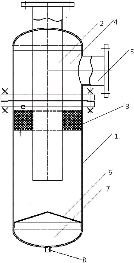
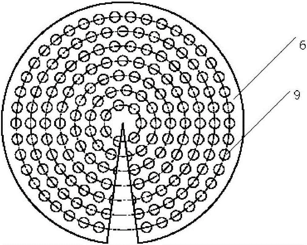
[0012] Referring to the accompanying drawings, a high-efficiency dehydration separator assembly includes a separator 1 and an air outlet pipe 2. A stainless steel wire mesh filter layer 3 is fixed between the inner wall of the separator 1 and the outer wall of the air outlet pipe 2, and is located on the stainless steel wire mesh. The inner cavity of the separator 1 above the filter layer 3 is an air cavity 4, the air cavity 4 is provided with an air inlet 5, and the inner wall of the bottom of the separator 1 is fixed with a flower-hole-shaped cone hydrophobic cap 6, and the flower-hole-shaped cone hydrophobic cap There is a water collecting chamber 7 under the water collecting chamber 7, and a drain port 8 is provided at the bottom of the water collecting chamber 7; the airflow direction of the air intake is consistent with the gravity direction of the condensed water, and there are Φ12mm holes evenly distributed on the flower-hole-shaped cone hydrophobic cap, and the flower-h...


PUM


Abstract

The invention discloses an efficient water removal separator assembly which comprises a separator and an air outlet pipe. The inner wall of the separator is fixedly provided with a stainless steel screen mesh filtering layer, a separator inner cavity located over the stainless steel screen mesh filtering layer serves as an air cavity, an air inlet is formed in the exterior of the air cavity, the inner wall of the bottom of the separator is fixedly provided with a flower-hole-shaped conical hydrophobic cap, a water gathering cavity is formed under the flower-hole-shaped conical hydrophobic cap, and a water draining port is formed in the cavity bottom of the water gathering cavity. According to the efficient water removal separator assembly, the separating efficiency is extremely high and is not influenced by air consumption load fluctuation, and the water removal effect is greatly superior to that of two existing traditional separators.

Description

technical field [0001] The invention relates to the field of water removal and separation, in particular to a high-efficiency water removal separator assembly. Background technique [0002] At present, there are two types of water separators on the market: water separators separated by tangential air inlet and centrifugal rotation, and water separators separated by wire mesh filter, baffle plate and hydrophobic cap. [0003] Tangential air inlet centrifugal rotary separation: It is required that the wind speed and flow rate must be around the point of the rated design parameter range, the greater the deviation, the worse the separation effect, and the water in the state of macromolecular particles is easy to enter the rear air point with the compressed air flow, and the The gas load of actual users is often unstable, so the water removal effect is poor. Although the latter can filter and condense water in the state of macromolecular particles into water in the state of larg...

Claims


Application Information

Patent Timeline
IPC IPC(8): B01D46/00
CPCB01D46/00
Inventor 许琎
Owner CHAO LV MOTIVE POWER ANHUI CO LTD
Why Eureka
Try Eureka