
Flip-flop clamp

A technology of flip-flops and fixtures, which is applied in household utensils, manufacturing tools, workpiece clamping devices, etc. It can solve problems such as low efficiency, loose shoe buckles, time-consuming and labor-intensive problems, and achieve improved quality, small perforation openings, and not easy to loosen Shedding effect

Inactive Publication Date: 2016-08-24
DAFENG CHENGGONG MACHINERY MFG FACTORY
View PDF0 Cites 0 Cited by
  • Summary
  • Abstract
  • Description
  • Claims
  • Application Information

AI Technical Summary

Problems solved by technology

However, there is a problem when dragging the plastic buckle. If the hole is not punched, the plastic buckle is difficult to pass through the sole, which is time-consuming and laborious, and the efficiency is not high.
However, if the hole is punched, it is easy to cause the buckle to loosen.

Method used


Image

  • Flip-flop clamp

Examples


Embodiment Construction

[0009] In order to further illustrate the technical means adopted by the present invention and the technical effects achieved, the following will be described in detail in conjunction with the accompanying drawings and preferred embodiments.

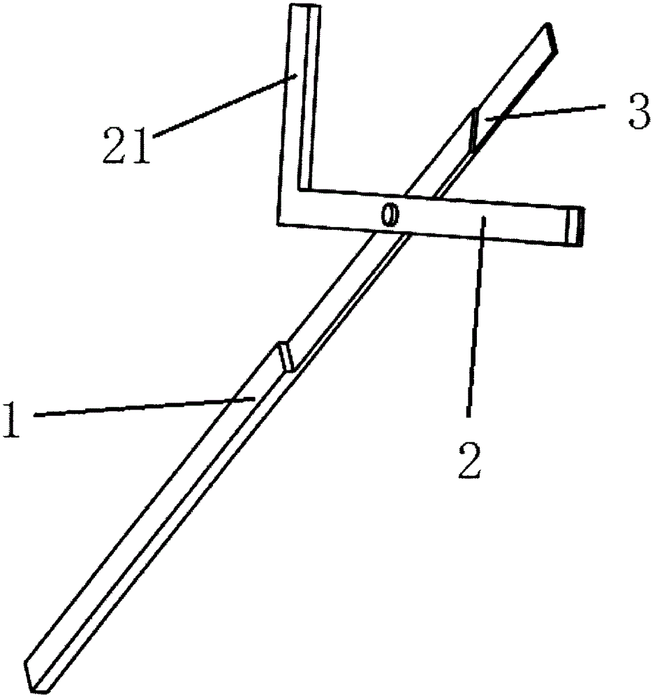
[0010] refer to figure 1 , is a schematic diagram of the three-dimensional structure of the flip-flop clamp of the present invention. In this embodiment, it includes a fixed part 1 and a rotating part 2, the fixed part 1 and the rotating part 2 are connected by a scissors-like movable shaft, and a bayonet 3 is provided near the front end of the fixed part and the rotating part , the rear end of the rotating part 2 extends laterally to form a rotating handle 21 .


PUM


Abstract

The invention provides a flip-flop clamp which comprises a fixing part and a rotation part. The fixing part is connected with the rotation part through a rotary shaft in a scissor shape; bayonets are formed in the positions, close to the front ends, of the fixing part and the rotation part correspondingly; and the back end of the rotation part extends toward the lateral side to form a rotation handle. The flip-flop clamp has the advantages of being rapid in perforation, being small in perforated opening, improving the production quality and the like.

Description

technical field [0001] The invention relates to a clamp, in particular to a flip-flop clamp. Background technique [0002] Now when processing flip-flops, it is necessary to fix the front plastic buckle through the entire sole. However, there is a problem when dragging the plastic buckle. If the hole is not punched, the plastic buckle is difficult to pass through the sole, which is time-consuming and labor-intensive, and the efficiency is not high. However, if the hole is punched, it is easy to cause the buckle to loosen. Contents of the invention [0003] The object of the present invention is to provide a flip-flop clamp with fast perforation and small perforation opening. [0004] In order to solve the above-mentioned technical problems, the present invention provides the following technical solutions: a flip flop clamp, which includes a fixed part and a rotating part, the fixed part and the rotating part are connected by a movable shaft in the shape of scissors, and ...

Claims


Application Information

Patent Timeline
IPC IPC(8): B25B11/00B29C65/56B29L31/50
Inventor 陈仲庆
Owner DAFENG CHENGGONG MACHINERY MFG FACTORY
Learn More