Bent RF connector housing

A technology of radio frequency connectors and shells, which is applied in the direction of connection, parts of connecting devices, electrical components, etc., can solve problems such as product corrosion, shell shedding, and irregular process operations, so as to facilitate expansion and deformation, not easy to loosen and fall off, Guarantee the effect of normal transmission

Pending Publication Date: 2018-12-25
ZHENJIANG HUAZHAN ELECTRONICS SCI & TECHCO
View PDF0 Cites 1 Cited by
  • Summary
  • Abstract
  • Description
  • Claims
  • Application Information

AI Technical Summary

Problems solved by technology

The shell of the bent connector is generally composed of a main shell and a secondary shell. The two are usually connected by silver welding, thread locking and interference press fit. For electroplating, due to the serious oxidation of the product at high temperature, the appearance quality of the product after electroplating is seriously reduced, and there may be subtle seams that cannot be integrated after silver welding. Cause corrosion, and if the structural design is unreasonable or the process operation is not standardized, it is easy to cause coating quality problems
The thread locking structure is highly reliable, and generally does not loosen and fall off when the occlusal thread is not loose. However, the processing cost of this structure is relatively high, and it is necessary to ensure that the thread does not loosen.
The interference press fit structure is simple and easy to operate, but the disadvantage is poor reliability. The fluctuation of the processing tolerance at the press fit of the two shells will directly affect the reliability after press fit. If the tolerance fit is loose, the two parts of the shell will separate and fall off. Press fit after high temperature It is also easy to loosen and fall off, causing major quality accidents

Method used


Image

  • Bent RF connector housing
  • Bent RF connector housing
  • Bent RF connector housing

Examples


Embodiment Construction

[0016] The present invention will be further described below in conjunction with drawings and embodiments.

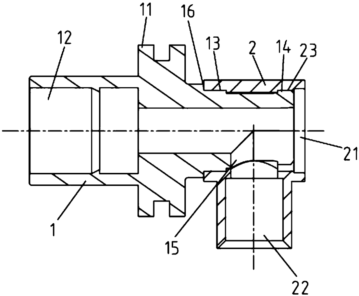
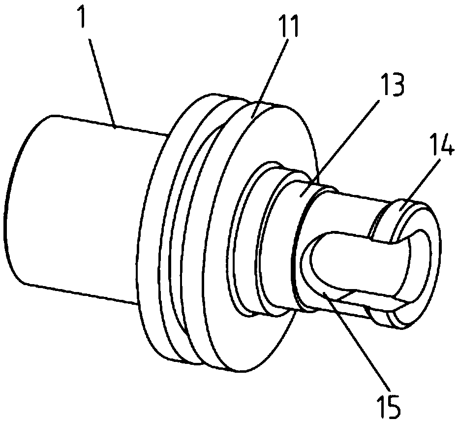
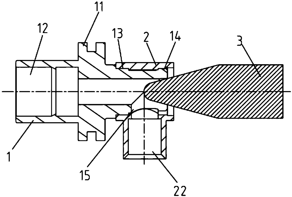
[0017] Such as figure 1 with figure 2 As shown, the present invention includes a main shell 1 and a secondary shell 2 fixed on the right end of the main shell 1 . The main housing 1 is a stepped shaft structure with a large left end and a small right end, and two anti-slip platforms 11 extend radially outward from the middle. The main housing 1 is provided with an axial through hole 12 of a stepped structure. An annular press-fit platform 13 is provided with an annular positioning platform 14 on the outside of its small end, and a U-shaped axial through groove 15 is also provided on one side of the outer peripheral surface of the small end of the main shell 1 . The sub-housing 2 is an overall structure of a cube at the upper end and a cylinder at the lower end. The sub-housing 2 is provided with an upper horizontal through-hole 21 and a lower-end vertical through-hol...


PUM


Abstract

The invention discloses a bent radio frequency connector housing, which comprises a main shell and an auxiliary shell, wherein the main shell is a stepped shaft structure with one larger end and a smaller end, an axial through hole with the stepped structure is arranged in the main shell, an annular press-fitting table is arranged inside the small end of the main shell, an annular positioning table is arranged outside the small end of the main shell, and an axial through groove is arranged on one side of the outer peripheral surface of the small end of the main shell; An inner side of the horizontal through hole of the upper end of the sub-shell is interference-fitted with an annular press fitting table, an annular positioning groove is arranged on the outer side of the horizontal throughhole of the upper end of the sub-shell, the annular positioning table is embedded in the annular positioning groove, and the vertical through hole of the lower end of the sub-shell is vertically communicated with the axial through hole of the main shell through the axial through groove. The invention has the advantages of simple structure, low cost and convenient operation. The two-stage fixed structure provides double safety for the connection of the main shell and the auxiliary shell, which ensures that the connection of the main shell and the auxiliary shell is stable and reliable, and is not easy to loose and fall off, so as to ensure the normal transmission of the radio frequency signal.

Description

technical field [0001] The invention relates to an angled radio frequency connector, in particular to an angled radio frequency connector housing with a reliable connection between a main housing and an auxiliary housing, and belongs to the technical field of electronic components. Background technique [0002] RF connectors are important electronic components in modern mobile communication networks. They are widely used in various environments and occasions of mobile communication. Right-angled connectors are also widely used as jumper plugs. The shell of the bent connector is generally composed of a main shell and a secondary shell. The two are usually connected by silver welding, thread locking and interference press fit. For electroplating, due to the serious oxidation of the product at high temperature, the appearance quality of the product after electroplating is seriously reduced, and there may be subtle seams that cannot be integrated after silver welding. Corrosion...

Claims


Application Information

Patent Timeline
Patent Type & Authority Applications(China)
IPC IPC(8): H01R13/502
CPCH01R13/502
Inventor 李斌芦坤
Owner ZHENJIANG HUAZHAN ELECTRONICS SCI & TECHCO
Why Eureka
Try Eureka