
Door lock anti-theft alarm device

An anti-theft alarm and door lock technology, applied in door leaves, building locks, window/door frames, etc., can solve problems such as poor anti-theft effect, and achieve the effect of not easy to open, wide application range, and good anti-theft effect.

Active Publication Date: 2018-04-10
DEYANG HENGDA LUMINAIRE MFG
View PDF5 Cites 0 Cited by
  • Summary
  • Abstract
  • Description
  • Claims
  • Application Information

AI Technical Summary

Problems solved by technology

[0005] The purpose of the present invention is to provide a door lock type anti-theft alarm device which has better anti-theft effect and is not easy to be destroyed by external means in view of the technical problems that the existing door lock type anti-theft alarm device is relatively easy to be destroyed by external means and has poor anti-theft effect. device

Method used


Image

  • Door lock anti-theft alarm device
  • Door lock anti-theft alarm device
  • Door lock anti-theft alarm device

Examples


Embodiment 1

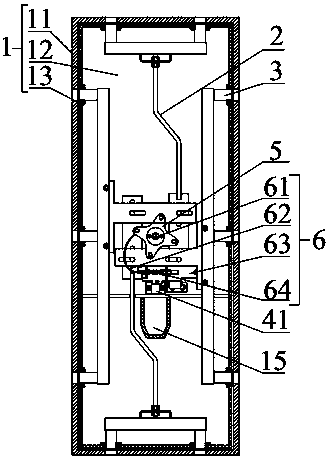
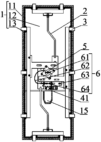
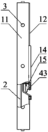
[0037] as attached Figure 1-6 As shown, the door lock type anti-theft alarm device includes a linkage lock cylinder, a pull rod assembly 2, a locking block 3 and a door frame assembly 1, and the door frame assembly 1 is provided with a chute 13 that matches the locking block 3, The pull rod assembly 2 is connected to the locking block 3, the interlocking lock core includes a first lock core 41 and a second lock core 42 that cooperate with each other, the pull rod assembly 2 is movably connected with the first lock core 41, and rotates The first lock core 41 can drive the pull rod assembly 2 to be connected to or separated from the second lock core 42. When the pull rod assembly 2 is connected to the second lock core 42, the second lock core 42 is rotated, so that The pull rod assembly 2 can drive the locking block 3 to move along the chute 13. The door frame assembly 1 includes a frame 11 and a first door panel 12 matched with the frame 1. The chute 13 runs through the first ...

Embodiment 2

[0040] Such as Figure 1-6 As shown, in the door-lock type anti-theft alarm device described in Embodiment 1, a connection assembly is provided between the first lock cylinder 41 and the second lock cylinder 42, and the connection assembly includes a rotating disk 5 and a pull wire mechanism 6, One end of the pull wire mechanism 6 is connected to the first lock core 41, and the other end is connected to the second lock core 42. The rotating disk 5 is connected to the pull rod assembly 2, and the first lock core 41 is rotated. The rotating disk 5 is connected to the second The lock cylinder 42 is connected or separated.

[0041] The door lock type anti-theft alarm device of this embodiment is used to connect the first lock core 41 and the second lock core 42 by setting the pull wire mechanism 6, and the rotation between the second lock core 42 and the rotating disk 5 is controlled by the rotation of the first lock core 41. The connection or separation between, so that when the...

Embodiment 3

[0044] Such as Figure 1-6 As shown, as in the door lock type anti-theft alarm device described in Embodiment 2, a spring 64 is arranged between the connecting block 63 and the push-pull wire 62, and the spring 64 exerts a spring force on the connecting block 63 to stop the rotation of the first lock. When the core 41 is locked, the spring 64 drives the connecting block 63 to move, so that the connecting block 63 pulls the limiting block 61 through the push-pull wire 62 to separate from the second lock cylinder 42 . By arranging the spring 64 between the connection block 63 and the push-pull wire 62, the first lock core 41 and the second lock core 42 must work simultaneously. It will automatically reset under the action of the spring 64, so that the limit block 61 and the second lock core 41 are separated, further making the rotation of the first lock core 41 and the second lock core 42 indispensable, and improving the anti-theft effect.

[0045] Preferably, at least one slid...


PUM


Abstract

The invention relates to an anti-theft alarm device in the anti-theft alarm field, in particular to a door lock type anti-theft alarm device. The door lock type anti-theft alarm device comprises an interlinked lock cylinder, a pull rod element, a lock-up block and a door frame element; the door frame element is provided with a chute which is matched with the lock-up block; the pull rod element is connected with the lock-up block; the interlinked lock cylinder comprises a first lock cylinder and a second lock cylinder which are mutually matched with each other; the pull rod element is movably connected with the first lock cylinder and rotates the first lock cylinder to drive the pull rod element to be connected with or separated from the second lock cylinder; when the pull rod element is connected with the second lock cylinder and rotates the second lock cylinder, the pull rod element is capable of driving the lock-up block to move along the chute; when the pull rod element is not connected with the second lock cylinder, the second lock cylinder can only be an idle one, therefore mutual operation between the two lock cylinders is not possible without either lock cylinder. The anti-theft alarm device achieves better anti-theft performance in a way of preventing anyone trying to open the door frame element from destroying the door frame element to enable the lock-up block to move along the chute through external means.

Description

technical field [0001] The invention relates to an anti-theft alarm device used in the field of anti-theft alarm, in particular to a door lock type anti-theft alarm device. Background technique [0002] Our common door lock type anti-theft device in our life is usually a lock set on the door. The lock cylinder of the lock set drives the lock rod to move, and is connected with the door frame fixed on the building to realize the anti-theft effect of the anti-theft device. [0003] However, the locks of the common door-lock anti-theft devices are relatively easy to be destroyed by external means, which makes the anti-theft effect invalid. On industrial equipment and facilities that require anti-theft, for example, communication base stations, high pole lighting and remote monitoring, etc. set in the field Equipment and facilities, which will be equipped with integrated power systems to provide uninterrupted power for equipment and facilities to ensure continuous operation of eq...

Claims


Application Information

Patent Timeline
Patent Type & Authority Patents(China)
IPC IPC(8): E05B63/14E05B35/12E05B15/00E05B15/10E05B15/02E06B1/52E06B3/70
CPCE05B15/00E05B15/02E05B15/108E05B35/12E05B63/143E05B63/146E06B1/52E06B3/70
Inventor 代明生
Owner DEYANG HENGDA LUMINAIRE MFG
Learn More