
Circulating defrosting system, refrigerator and defrosting method

A refrigerator and circulating pipeline technology, applied in the field of circulating defrosting systems, can solve the problems of long defrosting time, large power consumption, and large temperature fluctuations, and achieve low defrosting energy consumption, short defrosting time, and high temperature. The effect of small fluctuations

Inactive Publication Date: 2016-08-24
HEFEI HUALING CO LTD +1
View PDF5 Cites 10 Cited by
  • Summary
  • Abstract
  • Description
  • Claims
  • Application Information

AI Technical Summary

Problems solved by technology

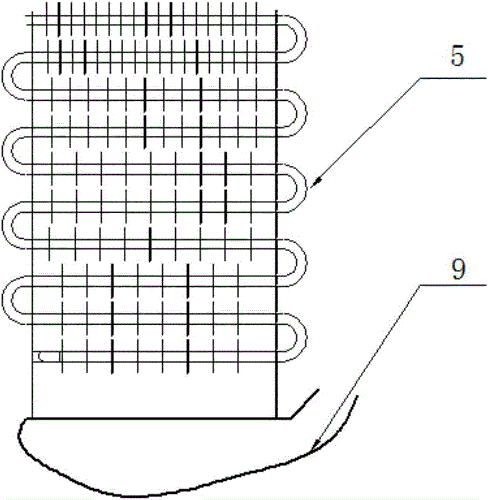
[0003] like figure 1 As shown, the existing electric heating defrost device 9 is heated outside the evaporator 5, and the frost layer is melted by radiation and natural convection, the efficiency is low, the power consumption is too large, and the frost layer does not fall off often, and the defrost layer is melted. The frosting time is long, and the defrosting period has a great influence on the temperature fluctuation in the compartment

Method used


Image

  • Circulating defrosting system, refrigerator and defrosting method
  • Circulating defrosting system, refrigerator and defrosting method
  • Circulating defrosting system, refrigerator and defrosting method

Examples


Embodiment Construction

[0031] The specific implementation manners of the present invention will be further described in detail below in conjunction with the accompanying drawings and embodiments. The following examples are used to illustrate the present invention, but are not intended to limit the scope of the present invention.

[0032] In the description of the present invention, it should be noted that the terms "center", "longitudinal", "transverse", "upper", "lower", "front", "rear", "left", "right", " The orientations or positional relationships indicated by "vertical", "horizontal", "top", "bottom", "inner", "outer", etc. are based on the orientation or positional relationships shown in the drawings, and are only for the convenience of describing the present invention and simplifying Describes, but does not indicate or imply that the device or element referred to must have a specific orientation, be constructed in a specific orientation, and operate in a specific orientation, and therefore sh...


PUM


Abstract

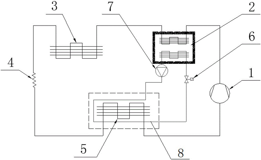
The invention discloses a circulating defrosting system which comprises a compressor, an evaporator, a condenser, a heat accumulator and a defrosting circulating pipeline. An inlet of the compressor is connected with an outlet of the evaporator. An inlet of the evaporator is connected with an outlet of the condenser through a capillary pipe. An inlet of the condenser is connected with a heat accumulating outlet of the heat accumulator. A heat accumulating inlet of the heat accumulator is connected with an outlet of the compressor. A heat releasing inlet of the heat accumulator is connected with an outlet of the defrosting circulating pipeline. A heat releasing outlet of the heat accumulator is connected with an inlet of the defrosting circulating pipeline. A water pump is arranged on a pipeline connecting the defrosting circulating pipeline and the heat releasing outlet. A normally-closed valve is arranged on a pipeline connecting the defrosting circulating pipeline and the heat releasing inlet. The defrosting circulating pipeline is attached to the outer side of a pipeline of the evaporator. The invention further provides a refrigerator and a defrosting method. By means of the circulating defrosting system, the refrigerator and the defrosting method, defrosting energy consumption can be lowered, defrosting time is short, and the influence on the temperature fluctuation of refrigerator chambers during defrosting is small.

Description

technical field [0001] The invention relates to the field of defrosting refrigerators, in particular to a cycle defrosting system, a refrigerator and a defrosting method. Background technique [0002] It is understood that most of the water vapor comes from the air. When people store food and open the refrigerator, the indoor air and the gas in the refrigerator exchange freely, and the humid air in the room quietly enters the refrigerator. Another part of the water vapor comes from the food stored in the refrigerator, such as cleaned vegetables and fruits in fresh-keeping boxes. The water in vegetables and other food evaporates and condenses into frost when it is cold. [0003] Such as figure 1 As shown, the existing electric heating defrost device 9 is heated outside the evaporator 5, and the frost layer is melted by radiation and natural convection, the efficiency is low, the power consumption is too large, and the frost layer does not fall off often, and the defrost laye...

Claims


Application Information

Patent Timeline
Patent Type & Authority Applications(China)
IPC IPC(8): F25D21/12
CPCF25D21/12F25D2321/1411
Inventor 吴默朱晓亮李骜方忠诚张贤中胡学洋龚勤勤
Owner HEFEI HUALING CO LTD
Learn More