
Heat storage defrosting system for cold storage air cooler and cold storage

A cooling fan and heat storage technology, which is applied in the field of cold storage equipped with heat storage defrosting system and heat storage defrosting system, can solve the problems of affecting food storage quality, high energy consumption of defrosting, and performance reduction of the unit, so as to avoid Large fluctuations in storage temperature, avoid storage temperature fluctuations, and increase the effect of heat storage temperature

Pending Publication Date: 2020-02-07
UNIV OF ELECTRONICS SCI & TECH OF CHINA ZHONGSHAN INST
View PDF0 Cites 2 Cited by
  • Summary
  • Abstract
  • Description
  • Claims
  • Application Information

AI Technical Summary

Problems solved by technology

[0003] At present, most of the defrosting methods in the cold storage are hot ammonia defrosting, hot water defrosting, manual defrosting, etc., which may easily cause storage temperature fluctuations, affect the quality of food storage, and may cause corruption and deterioration of items in severe cases
In addition, after the defrosting is completed, the liquid droplets remaining on the fin surface freeze rapidly when the unit resumes cooling, forming a layer of dense ice layer on the fin surface (called fin surface re-icing phenomenon), which rapidly reduces the performance of the unit
During the defrosting process, the heat of defrosting mainly comes from the power consumption of the compressor, so the energy consumption of defrosting is relatively high, and the high and low pressure switching of the system causes thermal shock to all components of the system, which reduces the reliability and service life of the refrigeration system
[0004] If the relative humidity of the storage environment is high, the speed of frosting on the surface of the air cooler will increase accordingly, resulting in shortened defrosting intervals
Frequent temperature fluctuations will seriously affect the storage quality of food, resulting in increased defrosting power consumption
[0005] The existing defrosting structure has the problem of high energy consumption. In addition to the problem of high energy consumption, the existing cold storage also has problems such as large storage temperature fluctuations and low system reliability.

Method used


Image

  • Heat storage defrosting system for cold storage air cooler and cold storage
  • Heat storage defrosting system for cold storage air cooler and cold storage
  • Heat storage defrosting system for cold storage air cooler and cold storage

Examples


Embodiment 1

[0035] A heat storage and defrosting system for a cold storage fan, comprising a refrigeration device, a heat storage device, and a heat release device.

[0036] The refrigerating device includes a compressor, a heat storage heat exchanger, a condenser, a throttling device, and an evaporator arranged in sequence, and the evaporator is connected to the compressor to form a refrigerating cycle for the refrigerating machine to circulate. In this embodiment, the condenser is a fin-tube heat exchanger, the throttling device is a capillary tube, and the evaporator is a fin-tube evaporator.

[0037] The heat storage device includes a heat storage tank, a heat storage pump, a heat storage heat exchanger, and a heat storage valve arranged in sequence, and the heat storage valve is connected to the heat storage tank to form a heat storage circulation loop for the heat storage agent to circulate. The heat storage valve adopts a solenoid valve. In this embodiment, the heat storage heat e...

Embodiment 2

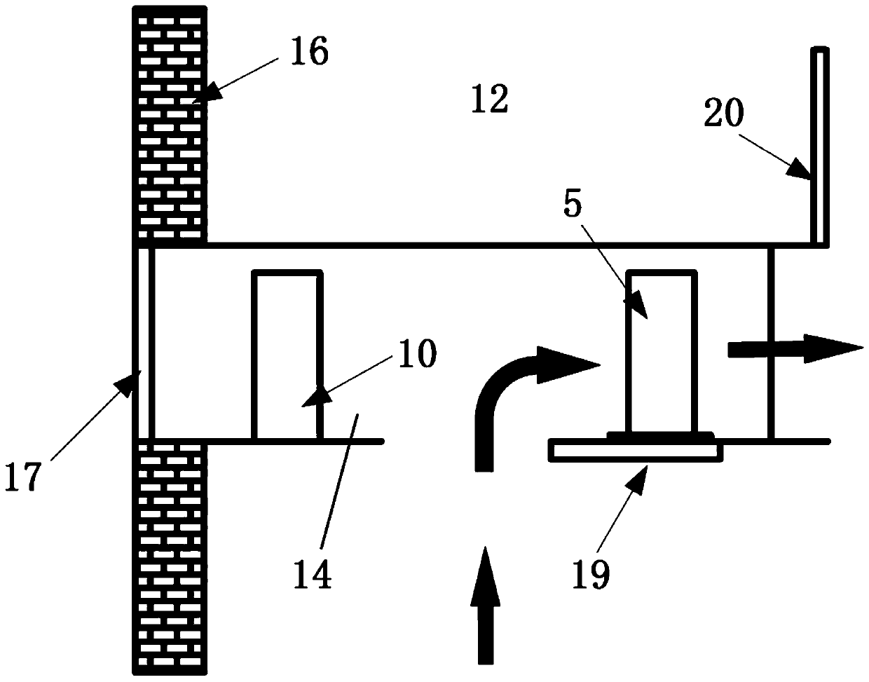
[0044] A cold storage, including a cold storage body, a cold storage machine room, and a heat storage and defrosting system for a cold storage fan according to Embodiment 1. The compressor, heat storage heat exchanger, condenser, throttling device, heat storage tank, heat storage pump, heat storage valve, heat release pump and heat release valve are set in the cold storage machine room, and the heat release heat exchanger and evaporator are set in the cold storage library body.

[0045] A cold storage also includes an airflow channel, a hydraulic door one, a hydraulic door two, a hydraulic door three, and a hydraulic door four. The hydraulic door is realized by controlling the translation of the insulation board through the hydraulic device. Among them, hydraulic door 1 and hydraulic door 2 open and close vertically, hydraulic door 3 opens and closes horizontally, and hydraulic door 4 opens and closes vertically. The airflow channel is U-shaped and arranged horizontally, inc...


PUM


Abstract

The invention relates to a heat storage defrosting system for a cold storage air cooler. The heat storage defrosting system comprises a refrigerating device, a heat storage device and a heat release device, wherein the refrigerating device comprises a compressor, a heat storage heat exchanger, a condenser, a throttling device and an evaporator which are sequentially arranged; the evaporator is connected into the compressor, and a refrigerating circulation loop is formed; the heat storage device comprises a heat storage tank, a heat storage pump, a heat storage heat exchanger and a heat storagevalve which are sequentially arranged; the heat storage valve is connected into the heat storage tank, and a heat storage circulation loop is formed; the heat release device comprises a heat storagetank, a heat release pump, a heat release heat exchanger and a heat release valve which are sequentially arranged; the heat release valve is connected into the heat storage tank, and a heat release circulation loop is formed; the refrigerating device and the heat storage device conduct heat exchange in the heat storage heat exchanger; and the refrigerating device and the heat release device conduct heat exchange through the evaporator and the heat release heat exchanger. The invention further relates to a cold storage. According to the heat storage defrosting system and the cold storage, energy consumption can be reduced, operation is more stable, temperature fluctuation in the cold storage is reduced, and the heat storage defrosting system and the cold storage belong to the technical field of refrigerating and quick freezing.

Description

technical field [0001] The invention relates to the technical field of refrigeration and quick-freezing, in particular to a heat storage defrosting system for a cold storage fan, and to a cold storage equipped with the heat storage defrosting system. Background technique [0002] In the field of fresh-keeping storage and quick-freezing of food, due to the low temperature and high humidity conditions, the surface of the air cooler is prone to frosting. The growth of the frost layer increases the heat transfer resistance and flow resistance between the evaporator and the low-temperature environment, making it difficult to maintain the required low-temperature environment, which affects the storage quality and freshness of food. In order to maintain the low-temperature working condition of the storage space, it is necessary to Periodic defrosting is performed on the surface of the evaporator to reduce heat transfer resistance and flow resistance. [0003] At present, most of t...

Claims


Application Information

Patent Timeline
Patent Type & Authority Applications(China)
IPC IPC(8): F25D21/12F25D29/00F25D21/14
CPCF25D21/12F25D21/002F25D21/14F25D2321/1441
Inventor 谭海辉潘巨华刘展
Owner UNIV OF ELECTRONICS SCI & TECH OF CHINA ZHONGSHAN INST
Learn More