Positioning rod used for fixing of lens support

A technology of positioning rod and lens holder, applied in the field of lens inspection frame, can solve the problems of large damage to the lens, single lens holder, etc., and achieve the effect of convenient flexibility

Inactive Publication Date: 2016-08-24
殷志成
View PDF7 Cites 1 Cited by
  • Summary
  • Abstract
  • Description
  • Claims
  • Application Information

AI Technical Summary

Problems solved by technology

[0003] The object of the present invention is to overcome the deficiencies of the prior art above, to provide a positioning rod for fixing the lens frame, and to clamp the lens by setting a pair of sliding wheels, which not only protects the side of the lens, but also enables the lens to be fixed. Rotation solves the problem that the lens holder in the prior art only has a single angle conversion, and the clamping of the lens is all directly contacted with metal, which causes great damage to the lens

Method used


Image

  • Positioning rod used for fixing of lens support
  • Positioning rod used for fixing of lens support

Examples


Embodiment Construction

[0011] In order to make the object, technical solution and advantages of the present invention more clear, the present invention will be further described in detail below in conjunction with the accompanying drawings and embodiments. It should be understood that the specific embodiments described here are only used to explain the present invention, not to limit the present invention.

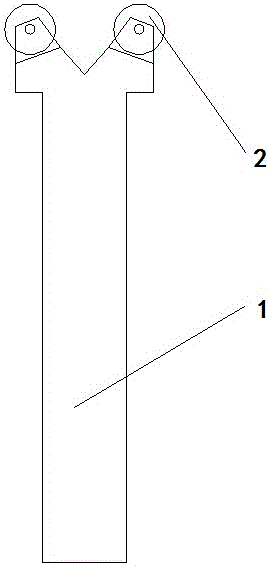
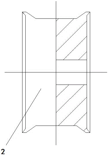
[0012] Such as figure 1 and 2 As shown, a positioning rod for fixing a lens frame includes a lens clamping rod 1 and a sliding wheel 2. One end of the lens clamping rod 1 is provided with a dovetail-shaped bump, and the dovetail-shaped bump is also provided with a fixing rod. The fixed frame of the sliding wheel 2, the sliding wheel 2 is a rubber wheel, and the end of the radial cross section is concave.

[0013] Among them, the sliding wheels 2 are distributed in pairs, and the lens is in contact with the concave surface of the sliding wheels 2. The lens is clamped by setting a pair of slidin...


PUM


Abstract

The invention relates to a positioning rod used for fixing of a lens support. The positioning rod comprises a lens clamping rod and roller wheels. One end part of the lens clamping rod is provided with a swallow tail-shaped protrusion, which is provided with fixing supports used for fixing the roller wheels. The roller wheels are rubber wheels, and have radial cross sections provided with concave end parts. The positioning rod provided by the invention is advantageous in that a pair of roller wheels are used for clamping the lens, and then the side edges of the lens are protected, and the lens can still rotate, and in addition, the flexibility during the clamping is facilitated; and the positioning rod is capable of solving the problems of the prior art that the lens support only has one rotation angle, the clamping of the lens adopts the metal for the direct contact, and the damage on the lens is large.

Description

technical field [0001] The invention relates to the field of lens detection frames, in particular to a positioning rod for fixing a lens frame. Background technique [0002] For the structure of the prior art lens detection frame, it is necessary to generate external force with the lens, which will have a certain impact on the surface of the lens. Moreover, the process of clamping the lens is more complicated for the common lens detection frame, and the detection efficiency is slow. The clamping accuracy of the lens cannot be guaranteed. Therefore, the lens is clamped by arranging a pair of sliding wheels, which not only protects the side of the lens, but also enables the lens to rotate, which is convenient for the flexibility of clamping, and solves the problem that the lens holder in the prior art only has a single angle conversion. , and the clamping of the lens is all directly contacted with metal, which has a problem of greater damage to the lens. Contents of the inv...

Claims


Application Information

Patent Timeline
Patent Type & Authority Applications(China)
IPC IPC(8): G01D11/16
CPCG01D11/16
Inventor 殷志成
Owner 殷志成
Why Eureka
Try Eureka