Display panel and display device

A technology for display panels and substrates, which is used in instruments, nonlinear optics, optics, etc. to achieve the effects of reducing aperture ratio, shortening delay time, and reducing resistance

Active Publication Date: 2016-08-24
SHANGHAI AVIC OPTOELECTRONICS +1
View PDF11 Cites 14 Cited by
  • Summary
  • Abstract
  • Description
  • Claims
  • Application Information

AI Technical Summary

Problems solved by technology

However, as the size of the liquid crystal display panel increases, the resistance of the common electrode also increases. The above method of covering the strip metal to reduce the resistance of the common electrode cannot meet the needs of existing liquid crystal display products.

Method used


Image

  • Display panel and display device
  • Display panel and display device
  • Display panel and display device

Examples


Embodiment Construction

[0017] The principles and features of the present application will be further described in detail below in conjunction with the drawings and embodiments. It should be understood that the specific embodiments described here are only used to explain related inventions, rather than to limit the invention. It should also be noted that, for ease of description, only parts related to the invention are shown in the drawings.

[0018] It should be noted that, in the case of no conflict, the embodiments in the present application and the features in the embodiments can be combined with each other. The present application will be described in detail below with reference to the accompanying drawings and embodiments.

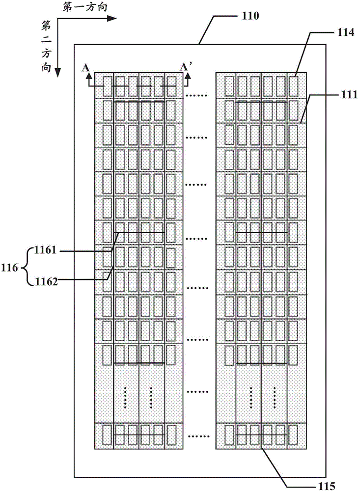
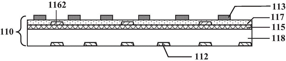
[0019] Please refer to Figure 1A and Figure 1B , which is a schematic structural diagram of an embodiment of the display panel of the present application. in, Figure 1B is along Figure 1A The cross-sectional view of the dotted line A-A' in.

[0020] Below, will com...


PUM


Abstract

The invention discloses a display panel and a display device. The display panel comprises a first base plate and a second base plate, wherein the second base plate is arranged in a way of being opposite to the first base plate; the first base plate comprises scanning wires, data wires, a pixel electrode layer, a common electrode layer and a metal passing wire; the data wires and the scanning wires are distributed in a crossed way to form a plurality of pixel regions; the pixel electrode layer comprises pixel electrodes positioned in each pixel region; the common electrode layer comprises a plurality of common electrodes corresponding to the pixel regions; the metal passing wire is electrically connected with each common electrode, and comprises crossed metal passing wire rows and metal passing wire lines; the pixel regions comprise light transmission regions and non-light-transmission regions; the metal passing wire and the non-light-transmission region are overlapped. The metal passing wire arranged in the non-light-transmission region of the pixel region in the display panel can reduce the resistance of the common electrode; the delay time of a voltage signal on the common electrode is shortened; meanwhile, the influence cannot be caused on the transmission rate of the display panel; the aperture opening ratio cannot be reduced; the display quality of the display panel is improved.

Description

technical field [0001] The present application relates to the field of display technology, and in particular to a display panel and a display device including the display panel. Background technique [0002] In recent years, liquid crystal display technology, as one of the mainstream display technologies, has been widely used in the display of TVs and mobile phones. Generally, a display panel in a liquid crystal device mainly includes a first substrate and a second substrate oppositely arranged, and a liquid crystal layer arranged between the first substrate and the second substrate. The above-mentioned first substrate can be an array substrate in a display panel, and the first substrate mainly includes scan lines, data lines, pixel electrodes, and common electrodes, etc., wherein the common electrodes can usually be made of transparent and conductive indium tin oxide (ITO) material As a result, the resistance of the common electrode itself is relatively large. Therefore, ...

Claims


Application Information

Patent Timeline
Patent Type & Authority Applications(China)
IPC IPC(8): G02F1/1343
CPCG02F1/134309G02F2201/121
Inventor 席克瑞崔婷婷
Owner SHANGHAI AVIC OPTOELECTRONICS
Why Eureka
Try Eureka