Optical color wheel component and optical color wheel thereof

A color wheel and optical technology, used in optics, instruments, projection devices, etc., can solve the problems of wind shear noise, up to 80 to 90 decibels, etc., to reduce noise and improve transmittance.

Inactive Publication Date: 2016-08-24
TAIWAN COLOR OPTICS
View PDF8 Cites 13 Cited by
  • Summary
  • Abstract
  • Description
  • Claims
  • Application Information

AI Technical Summary

Problems solved by technology

Although this way of opening the slot can completely transmit the blue laser light without reducing the efficiency of the light source, however, this way of opening the slot to allow the blue laser to transmit is prone to wind shear due to the high-speed rotation of the color wheel. Noise, for example, its noise level may be as high as 80 to 90 decibels

Method used


Image

  • Optical color wheel component and optical color wheel thereof
  • Optical color wheel component and optical color wheel thereof
  • Optical color wheel component and optical color wheel thereof

Examples


no. 1 example 〕

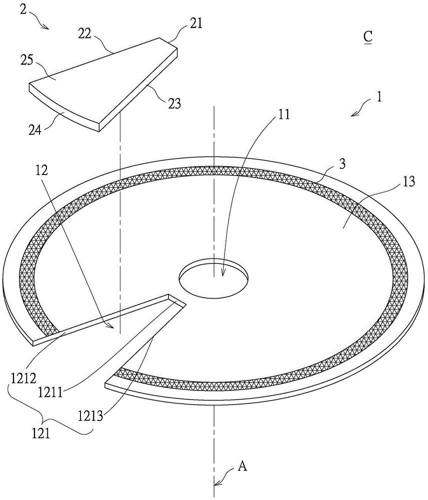
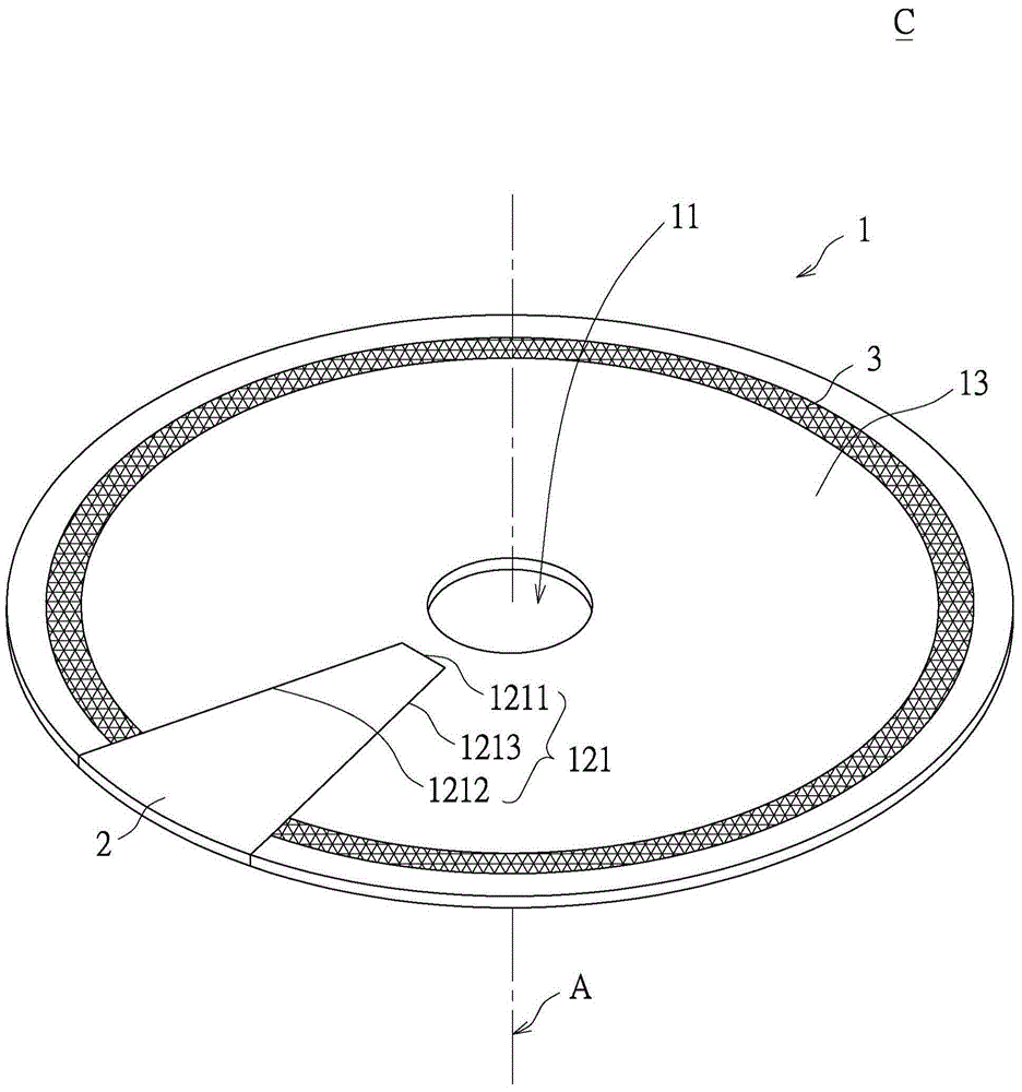
[0050] First, see Figure 1A to Figure 1B as shown, Figure 1A It is a three-dimensional exploded schematic view of the optical color wheel assembly and its optical color wheel according to the first embodiment of the present invention, Figure 1B It is a three-dimensional combined schematic view of the optical color wheel assembly and its optical color wheel according to the first embodiment of the present invention.

[0051] The first embodiment of the present invention provides an optical color wheel C, which includes a base unit 1, a light-transmitting unit 2, and a fluorescent unit 3. The base unit 1 includes a central hole 11, a central axis A, a transparent The light area 12 and a reflection area 13, the central hole 11 is arranged on the base unit 1, and is arranged along the central axis A, and the light transmission area 12 and the reflection area 13 are connected to each other to surround the central axis A, wherein the light transmission area 12 There is a through...

no. 2 example

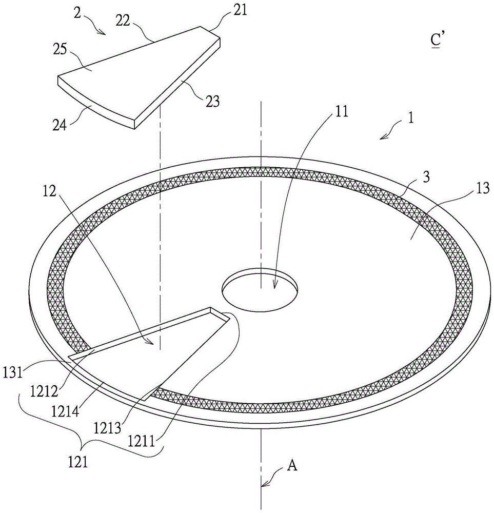
[0057] First, see Figure 2A to Figure 2B as shown, Figure 2A It is a perspective exploded view of the optical color wheel assembly and its optical color wheel according to the second embodiment of the present invention, Figure 2B It is a three-dimensional schematic diagram of the optical color wheel assembly and its optical color wheel according to the second embodiment of the present invention. Depend on Figure 1A and Figure 2A From the comparison, it can be seen that the biggest difference between the second embodiment and the first embodiment is that: the base unit 1 of the second embodiment further has a side end 131 . Through the design of the side end portion 131 , the light-transmitting unit can be tightly fitted in the through hole 121 more firmly.

[0058] Specifically, the second embodiment of the present invention provides an optical color wheel C', which includes a base unit 1, a light-transmitting unit 2, and a fluorescent unit 3. The base unit 1 includes ...

no. 3 example

[0067] First, see Figure 3A to Figure 3B as shown, Figure 3A It is a three-dimensional combination schematic diagram of the optical color wheel assembly and its optical color wheel according to the third embodiment of the present invention, Figure 3B It is a three-dimensional exploded schematic diagram of the optical color wheel assembly and the optical color wheel according to the third embodiment of the present invention. Depend on Figure 3A and Figure 2A It can be seen from the comparison that the biggest difference between the third embodiment and the second embodiment is that the optical color wheel (C', C") provided by the second embodiment of the present invention can be applied to the optical color wheel assembly of the projector On S. The third embodiment of the present invention provides an optical color wheel assembly S, which includes an optical color wheel C″, a driving element 4 and a spacer unit 5 .

[0068] As above, please also refer to Figure 2C As...


PUM


Abstract

The present invention provides an optical color wheel component and an optical color wheel thereof. The optical color wheel comprises a base unit, a light-transmitting unit, and a fluorescent unit. The base unit comprises a central hole, a central axis, a light-transmitting region, and a reflective region. The central hole is arranged along the central axis. The light-transmitting region and the reflective region are connected to go around the central axis. The light-transmitting region is provided with a through hole. The light-transmitting unit is arranged in the through hole and is surrounded by the through hole. The fluorescent unit is arranged on the reflective region and goes around the central axis. The invention also provides an optical color wheel component.

Description

technical field [0001] The invention relates to an optical color wheel assembly and the optical color wheel thereof, in particular to an optical color wheel assembly and the optical color wheel used in a projection device. Background technique [0002] One of the characteristics of the projector is that it is not limited by the size of the screen because it does not require a fixed screen. As long as there is a flat surface available for projecting images, large-size images can be easily projected. Therefore, it has been widely used in various fields, such as using a projector to enlarge the picture to be projected in large-scale conference speeches, or being used in a home theater group. [0003] Currently common projectors use a color wheel (color filter or color wheel) driven by a high-speed motor inside the projector to separate and process colors. However, in the traditional color wheel structure, the part used for the transmission of the blue laser light source is mos...

Claims


Application Information

Patent Timeline
Patent Type & Authority Applications(China)
IPC IPC(8): G03B21/14G03B21/20
Inventor 王志峰张永朋黄国胤陈信安郑韦治
Owner TAIWAN COLOR OPTICS
Why Eureka
Try Eureka