Tray, carrying device, and semiconductor processing equipment

A carrier device and tray technology, which is applied in semiconductor/solid-state device manufacturing, metal material coating process, gaseous chemical plating, etc., can solve the problems of high investment cost, inability to limit the position of the substrate S, and crushing of the substrate. Achieve the effect of improving reliability and reducing the risk of crushing the radial dimension limit

Inactive Publication Date: 2016-08-24
BEIJING NAURA MICROELECTRONICS EQUIP CO LTD
View PDF4 Cites 2 Cited by
  • Summary
  • Abstract
  • Description
  • Claims
  • Application Information

AI Technical Summary

Problems solved by technology

[0004] In practical applications, it is found that during the process of transporting the tray 12 and loading the substrate S into the groove 121, it is easy to cause deviations in the placement direction of the substrate S, such as Figure 2a As shown, this will cause part of the sidewall of the substrate S to be in close contact with part of the sidewall of the groove 121, and the corners on the sidewall of the substrate S will be in close contact with the sidewall of the above-mentioned straight line of the groove 121, wherein the corners It is formed by a series of planes and curved surfaces, that is, the substrate S is clamped by the groove 121. In this case, if the thermal expansion coefficient of the substrate S is greater than the thermal expansion coefficient of the groove 121, during the process The substrate S will be crushed due to the limitation of the radial dimension of the groove 121
[0005] For this reason, the above-mentioned problem can be solved by increasing the radial dimension of each groove 121, but there will be the following problems: First, if the deviation of the placement direction of the substrate S is large, there will be problems such as Figure 2b The situation shown, which is the same as Figure 2a The situation shown is similar, the substrate S is stuck in the groove 121, so there is still a risk of the substrate being crushed; secondly, when the number of grooves 121 on the tray 12 remains unchanged, it is necessary to increase the size of the tray 12 size, which requires the improvement of other components used in conjunction with the pallet 12, resulting in large investment costs
In addition, the above-mentioned problem is solved by setting the groove 121 into a circular structure, such as Figure 2c As shown, this will make the groove 121 unable to define the position of the substrate S, that is, the position of the substrate S in the groove 121 is not limited, so that the requirements cannot be met.

Method used


Image

  • Tray, carrying device, and semiconductor processing equipment
  • Tray, carrying device, and semiconductor processing equipment
  • Tray, carrying device, and semiconductor processing equipment

Examples


Embodiment Construction

[0033] In order for those skilled in the art to better understand the technical solution of the present invention, the tray, the carrying device and the semiconductor processing equipment provided by the present invention will be described in detail below with reference to the accompanying drawings.

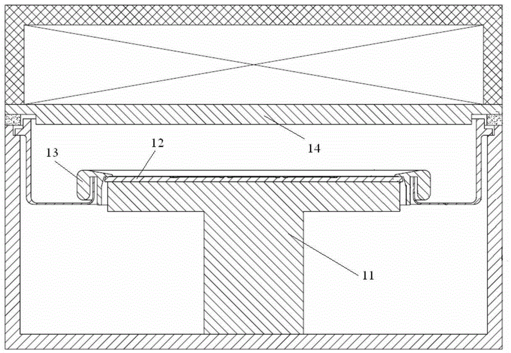
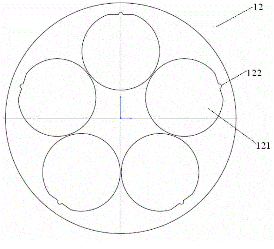
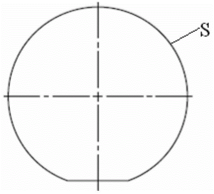
[0034] The tray provided in this embodiment is provided with at least one groove for accommodating the substrate and defining the placement direction of the substrate, the radial cross-sectional contour shape of the groove and the radial cross-sectional contour shape of the substrate are similar figures, The sidewall of the groove has a first corner, and the sidewall of the substrate has a second corner corresponding to the first corner. The so-called corner refers to a sharp corner formed by the contact of two surfaces. A first recess is provided at the position of each first corner on the side wall of the groove, and each first recess is used to accommodate the second corner of ...


PUM

PropertyMeasurementUnit
radiusaaaaaaaaaa

Abstract

The present invention provides a tray, a carrying device, and semiconductor processing equipment. The tray is provided with at least groove for receiving a substrate and limiting the placement direction of the substrate. The radial cross-sectional profile shape of the groove and the radial cross-sectional profile shape of the substrate are similar figures. The side wall of the groove is provided with first edges, and the side wall of the substrate is provided with second edges corresponding to the first edges. Each edge in the groove side wall is provided with a first concave part which is used for receiving the second edge of the substrate when the substrate has a placement direction deviation and is not in contact with the substrate. According to the tray provided by the invention, the risk of crush of the substrate under the radial size limitation of the groove can be effectively reduced, thus the waste of the substrate can be avoided, and the economic efficiency is improved.

Description

technical field [0001] The invention belongs to the technical field of semiconductor equipment manufacturing, and in particular relates to a tray, a carrying device and semiconductor processing equipment. Background technique [0002] Physical vapor deposition equipment is used to deposit thin films on substrates located within it, and its process environment is generally vacuum. Figure 1a For a schematic diagram of the reaction chamber structure of a typical physical vapor deposition equipment, see Figure 1a , the reaction chamber 10 is provided with a base 11 , a tray 12 and a pressure ring 13 . Wherein, the base 11 is arranged at the bottom of the reaction chamber 10, and has a heating function, which is used to indirectly heat and control the temperature of the substrate on the tray 12 through the tray 12, so that the substrate reaches the temperature required by the process; the tray 12 is provided with a plurality of grooves for carrying the substrate to improve the ...

Claims


Application Information

Patent Timeline
Patent Type & Authority Applications(China)
IPC IPC(8): H01L21/673C23C16/458
Inventor 武学伟张军董博宇郭冰亮马怀超
Owner BEIJING NAURA MICROELECTRONICS EQUIP CO LTD
Why Eureka
Try Eureka