Circulator

A technology of circulators and substrates, applied in the field of circulators, can solve the problems of high processing technology requirements, loose ferrite material structure, poor batch processing consistency, etc., and achieve the effect of improving consistency and reducing difficulty

Active Publication Date: 2016-08-24
HUAWEI TECH CO LTD +1
View PDF5 Cites 13 Cited by
  • Summary
  • Abstract
  • Description
  • Claims
  • Application Information

AI Technical Summary

Problems solved by technology

However, the circulator in the prior art sputters the microstrip circuit on the ferrite because the lines of the high-frequency microstrip circuit are thin, the structure of the ferrite material is loose, and the processing technology requirements are high, resulting in poor batch processing consistency.

Method used


Image

  • Circulator
  • Circulator
  • Circulator

Examples


Embodiment Construction

[0039] In order to make the purpose, technical solutions and advantages of the present invention clearer, the present invention will be further described in detail below in conjunction with the accompanying drawings. Obviously, the described embodiments are only some of the embodiments of the present invention, rather than all of them. Based on the embodiments of the present invention, all other embodiments obtained by persons of ordinary skill in the art without making creative efforts belong to the protection scope of the present invention.

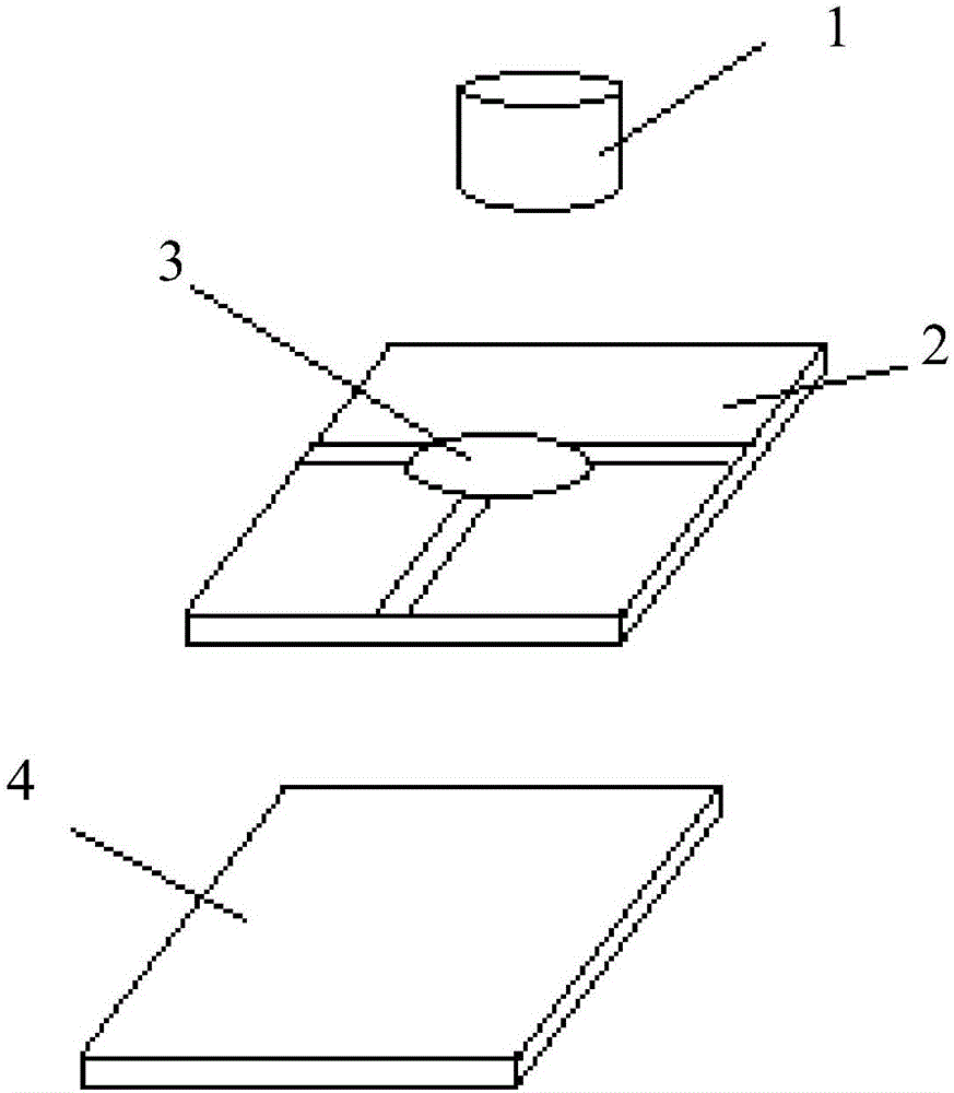
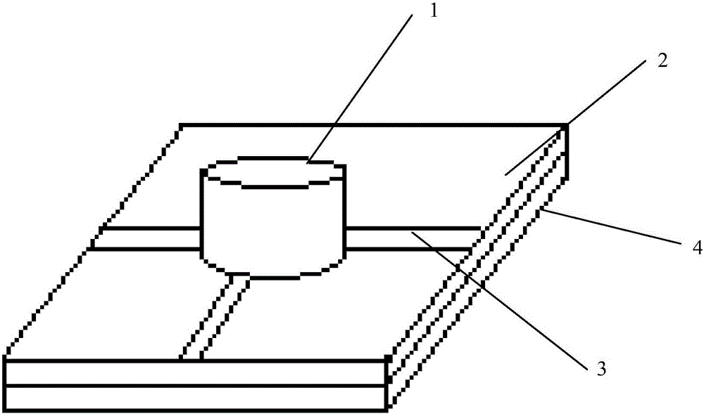
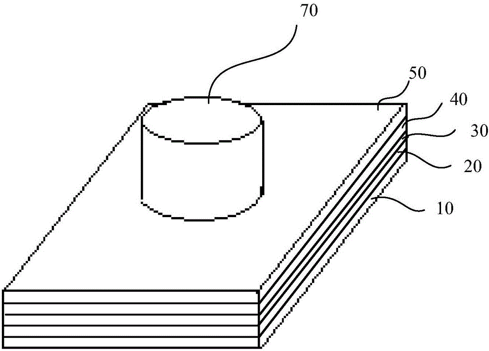
[0040] Such as image 3 As shown, the embodiment of the present invention provides a circulator, and the circulator includes:

[0041] Ground layer 10;

[0042] The microstrip circuit layer 30 includes a first substrate, microstrip circuits symmetrically arranged on opposite sides of the first substrate, and the two microstrip circuits are connected through the first metallized through hole 3013;

[0043] The first ferrite and the sec...


PUM


Abstract

The invention, which relates to the technical field of communication, discloses a circulator comprising a grounding layer, a microstrip circuit layer, a first ferrite, a second ferrite, and a permanent magnet. The microstrip circuit layer includes a first substrate and microstrip circuits arranged at two opposite surfaces of the first substrate symmetrically; and the two microstrip circuits are communicated by a first metalized through hole. The first ferrite and the second ferrite arranged coaxially are connected with the grounding layer; and the two ferrites and the two microstrip circuits correspond to each other one by one. The permanent magnet, the first ferrite and the second ferrite are arranged coaxially; and the permanent magnet is arranged above the second ferrite. According to the embodiment, the microstrip circuits are realized by the metal plating layer etched on the substrate instead of being sputtered on the ferrites directly. Therefore, the process difficulty is reduced and the consistency of batch processing is improved.

Description

technical field [0001] The present invention relates to the technical field of communication, in particular to a circulator. Background technique [0002] As the frequency of 5G communication equipment increases, the power decreases, and the number of channels increases in the future, traditional microstrip ferrite circulators in the prior art, such as figure 1 As shown, the microstrip circuit 3 is sputtered on the ferrite 2, the ferrite 2 is welded to the metal substrate 4, and the permanent magnet 1 is glued on the top of the microstrip circuit 3 to realize it. The overall structure after the combination is shown in figure 2 . However, the circulators in the prior art sputter the microstrip circuit on the ferrite because the lines of the high-frequency microstrip circuit are thin, the structure of the ferrite material is loose, and the processing technology requirements are high, resulting in poor consistency in batch processing. Contents of the invention [0003] The...

Claims


Application Information

Patent Timeline
Patent Type & Authority Applications(China)
IPC IPC(8): H01P1/38H01P1/387
CPCH01P1/38H01P1/387
Inventor 张如李扬兴张华锋高男
Owner HUAWEI TECH CO LTD
Why Eureka
Try Eureka