
Operation state control method and device of switch

A technology of operating status control and switches, applied in the field of switches, can solve problems such as power consumption, power consumption, and lack of automatic shutdown, and achieve the effects of preventing power consumption waste, saving power consumption, and long service life

Inactive Publication Date: 2016-08-24
SHENZHEN ALLWINS TECH
View PDF5 Cites 0 Cited by
  • Summary
  • Abstract
  • Description
  • Claims
  • Application Information

AI Technical Summary

Problems solved by technology

[0003] When the switch is working, it will generate a certain amount of power consumption. Since the current switch does not have the function of automatic shutdown, if the switch is not turned off manually, the switch will always be in the working state, which generates unnecessary power consumption. , and the long-term working status of the switch will accelerate the aging of the switch, thereby affecting the service life of the switch

Method used


Image

  • Operation state control method and device of switch
  • Operation state control method and device of switch
  • Operation state control method and device of switch

Examples


Embodiment 1

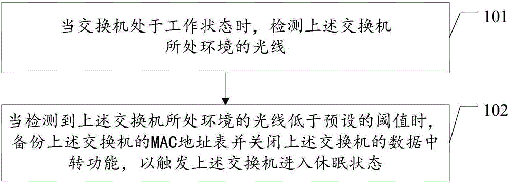
[0020] An embodiment of the present invention provides a method for controlling the operating state of a switch, please refer to figure 1 , the switch operating state control method in the embodiment of the present invention includes:

[0021] Step 101, when the switch is in the working state, detect the light of the environment where the switch is located;

[0022] In the embodiment of the present invention, when the switch is in the working state, the light of the environment where the switch is located is detected periodically or continuously.

[0023] Specifically, a light sensor may be used to detect light in the environment where the switch is located.

[0024] Step 102, when it is detected that the light in the environment where the above-mentioned switch is located is lower than a preset threshold, back up the MAC address table of the above-mentioned switch and close the data transfer function of the above-mentioned switch, so as to trigger the above-mentioned switch ...

Embodiment 2

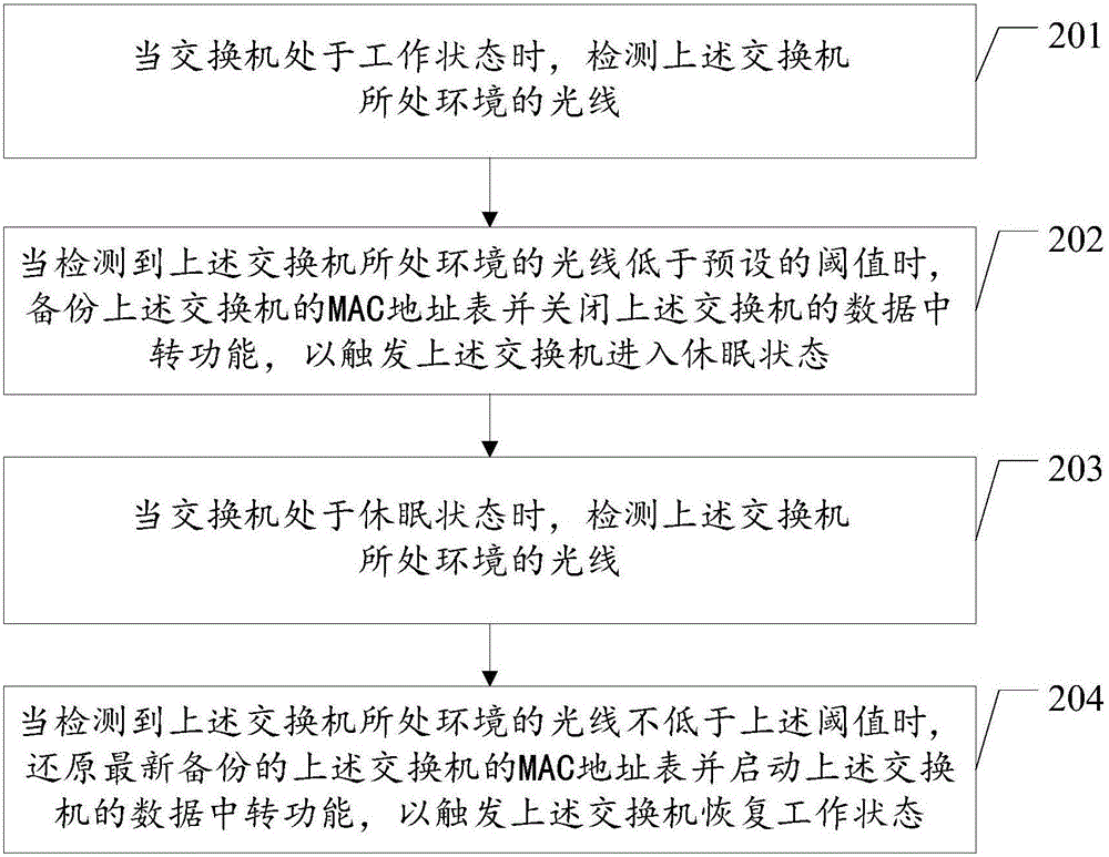
[0032] The difference between the embodiment of the present invention and the first embodiment is that in the embodiment of the present invention, after the switch enters the sleep state, the automatic recovery of the working state of the switch is realized by detecting the light in the environment where the switch is located.

[0033] like figure 2 As shown, the switch operating state control method in the embodiment of the present invention includes:

[0034] Step 201, when the switch is in the working state, detect the light of the environment where the switch is located;

[0035] In the embodiment of the present invention, when the switch is in the working state, the light of the environment where the switch is located is detected periodically or continuously.

[0036] Specifically, a light sensor may be used to detect light in the environment where the switch is located.

[0037] Step 202, when it is detected that the light in the environment where the above-mentioned ...

Embodiment 3

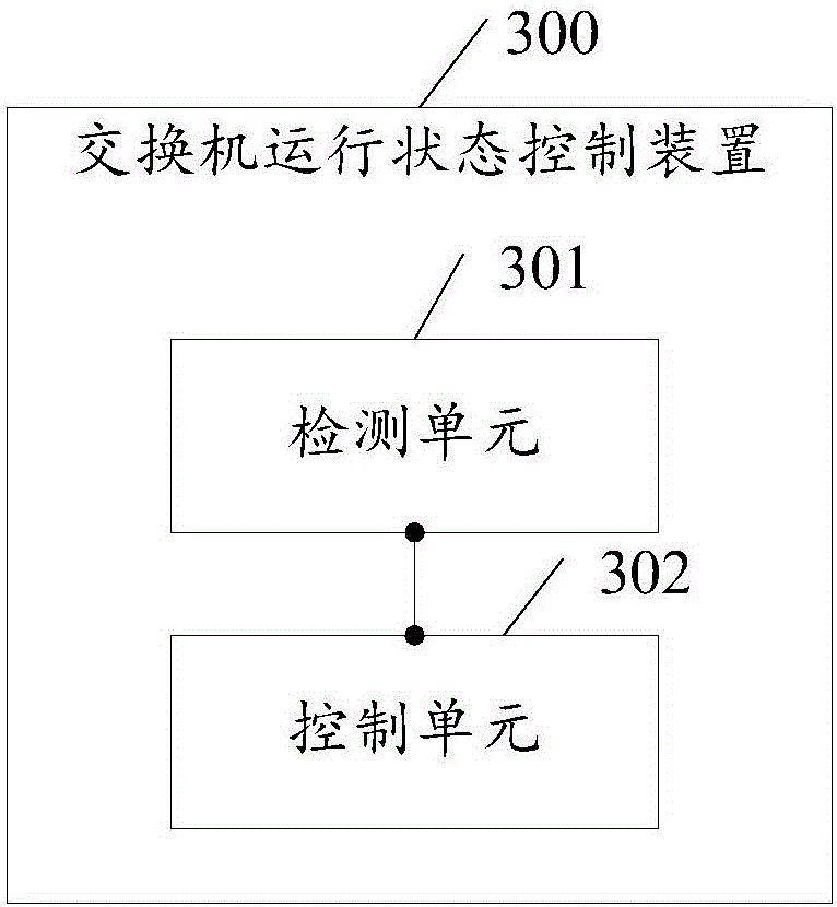
[0050] An embodiment of the present invention provides a switch operating state control device, please refer to image 3 , the switch operating state control device 300 in this embodiment of the present invention includes:


PUM


Abstract

The invention discloses an operation state control method and device of a switch. The operation state control method of the switch comprises following steps of detecting the light of an environment in which the switch is located when the switch is in a working state; and backing up a media access control MAC address table of the switch and closing a data transfer function of the switch when it is detected that the light of the environment in which the switch is located is lower than a preset threshold value, thus triggering the switch to enter a sleep sate, wherein the MAC address table comprises MAC addresses of hosts connected with the switch and serial numbers of the ports of the switch correspondingly connected with the hosts. According to the technical scheme provided by the invention, the switch is enabled to sleep automatically, and the power consumption of the switch is saved.

Description

technical field [0001] The invention relates to the technical field of switches, in particular to a method and device for controlling the operating state of a switch. Background technique [0002] A switch is a network device used for electrical (optical) signal forwarding, which can provide an exclusive electrical signal path for any two network nodes connected to the switch. [0003] When the switch is working, it will generate a certain amount of power consumption. Since the current switch does not have the function of automatic shutdown, if the switch is not turned off manually, the switch will always be in the working state, which generates unnecessary power consumption. , and the long-term working status of the switch will accelerate the aging of the switch, thereby affecting the service life of the switch. SUMMARY OF THE INVENTION [0004] The invention provides a method and device for controlling the operating state of a switch, which are used to enable the switch...

Claims


Application Information

Patent Timeline
Patent Type & Authority Applications(China)
IPC IPC(8): H04L12/12
CPCH04L12/12Y02D30/50
Inventor 周鸣华夏云梁大衡黄宁新封枫甘钧兆彭志伟唐大明
Owner SHENZHEN ALLWINS TECH
Learn More