Ceramic electric soldering iron

A technology of electric soldering iron and ceramics, which is applied in the direction of soldering iron, metal processing equipment, welding equipment, etc. It can solve the problems of unguaranteed grounding voltage, damage to internal equipment of electric soldering iron, and shortened service life. It achieves low price, eliminates static electricity, and avoids damage. damage effect

Pending Publication Date: 2021-11-26
CHONGQING LE MARK CERAMIC TECH CO LTD
View PDF1 Cites 1 Cited by
  • Summary
  • Abstract
  • Description
  • Claims
  • Application Information

AI Technical Summary

Problems solved by technology

[0002] At present, electric soldering iron is an indispensable tool in the electrical industry and electronic production. It is used for welding components and their wires. Electrostatic discharge (ESD) is generated due to charge transfer caused by objects with different electrostatic potentials approaching each other or in direct contact during use. ), ESD will cause damage to the internal equipment of the electric soldering iron and reduce the service life. my country is a processing base of electronic products, and there are many electronic product processing enterprises all over the country. Most of the ESD control work of these enterprises has not been established in accordance with American standards. ESD20.20 scheme requires grounding voltage <2mV and grounding resistance <2Ω
[0003] In the prior art, anti-static is carried out by directly grounding the shell or using a ceramic heating element. For example, the patent application number CN200520065808.4 discloses an AC-DC dual-purpose energy-saving anti-static constant-temperature silicon nitride electric soldering iron. , Welding nozzle, stainless steel sleeve, heat-insulating ceramic tube, inclined-plane heat-insulating ceramic tube and handle. There are 2 lead-out electrodes, and the electrostatic protection of the heating element cannot guarantee that the grounding voltage is <2mV and the grounding resistance is <2Ω

Method used


Image

  • Ceramic electric soldering iron

Examples


Embodiment

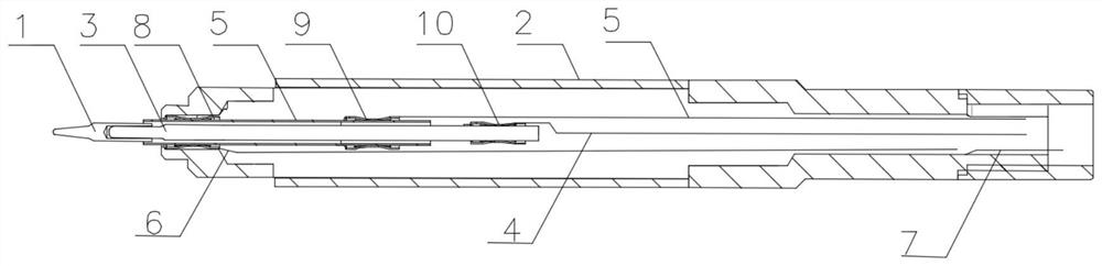
[0018] Such as figure 1 As shown, a ceramic electric soldering iron includes a soldering iron head 1, a handle 2, a ceramic heating element 3, a positive lead 4, a negative lead 5, a lead 6 and a ground wire 7, and the front end of the ceramic heating element 3 is connected to the soldering iron tip 1 , the handle 2 wraps the ceramic heating element 3 and the soldering iron tip 1, the soldering iron tip 1 passes through the front end of the handle 2, the negative lead 5 is connected to the soldering iron tip 1, the negative lead 5 Lead out from the middle of the ceramic heating element 3, the negative electrode lead 5 and the positive electrode lead 4 form a loop in the ceramic heating element 3, and heat the ceramic heating element 3, the front end of the ceramic heating element 3 The lead wire 6 is drawn from the negative lead wire 5, and the lead wire 6 is connected to the control and detection center to detect the grounding voltage and grounding resistance. The closer the ...


PUM


Abstract

The invention relates to the technical field of heating equipment, and discloses a ceramic electric soldering iron. The ceramic electric soldering iron comprises a soldering bit, a handle, a ceramic heating body, a positive wire and a negative wire, and is characterized by further comprising a wire and a ground wire, wherein the negative wire is connected to the soldering bit, the positive wire is connected to the ceramic heating body, the wire is connected to the cathode wire at the front end of the ceramic heating body, the wire is connected with a control detection center (capable of detecting grounding voltage and grounding resistance), and the ground wire is connected with the handle. The ceramic electric soldering iron has the advantage of determining whether the grounding voltage is less than 2 mV and the grounding resistance is less than 2 Ohm.

Description

technical field [0001] The invention relates to the technical field of heating equipment, in particular to a ceramic electric soldering iron. Background technique [0002] At present, electric soldering iron is an indispensable tool in the electrical industry and electronic production. It is used for welding components and their wires. Electrostatic discharge (ESD) is generated due to charge transfer caused by objects with different electrostatic potentials approaching each other or in direct contact during use. ), ESD will cause damage to the internal equipment of the electric soldering iron and reduce the service life. my country is a processing base of electronic products, and there are many electronic product processing enterprises all over the country. Most of the ESD control work of these enterprises has not been established in accordance with American standards. The ESD20.20 scheme requires the grounding voltage to be less than 2mV and the grounding resistance to be les...

Claims


Application Information

Patent Timeline
Patent Type & Authority Applications(China)
IPC IPC(8): B23K3/03
CPCB23K3/03B23K3/0346
Inventor 雷彼得
Owner CHONGQING LE MARK CERAMIC TECH CO LTD
Why Eureka
Try Eureka