Anti-slip device for tire, and body for anti-slip device for tire

An anti-skid device and tire technology, applied in anti-skid devices, tire parts, transportation and packaging, etc., can solve the problems of high cost, heavy physical labor, and high fuel consumption of snow tires, and achieve low manufacturing costs and simple main body Effect

Active Publication Date: 2016-08-24
KAGA CO LTD
View PDF9 Cites 0 Cited by
  • Summary
  • Abstract
  • Description
  • Claims
  • Application Information

AI Technical Summary

Problems solved by technology

However, snow tires cost more and have higher fuel consumption compared to summer tires
In addition, conventional metal chains are not easy to install, especially in the case of large vehicles, and their installation requires heavy physical labor.

Method used


Image

  • Anti-slip device for tire, and body for anti-slip device for tire
  • Anti-slip device for tire, and body for anti-slip device for tire
  • Anti-slip device for tire, and body for anti-slip device for tire

Examples


no. 1 example

[0080] "summary"

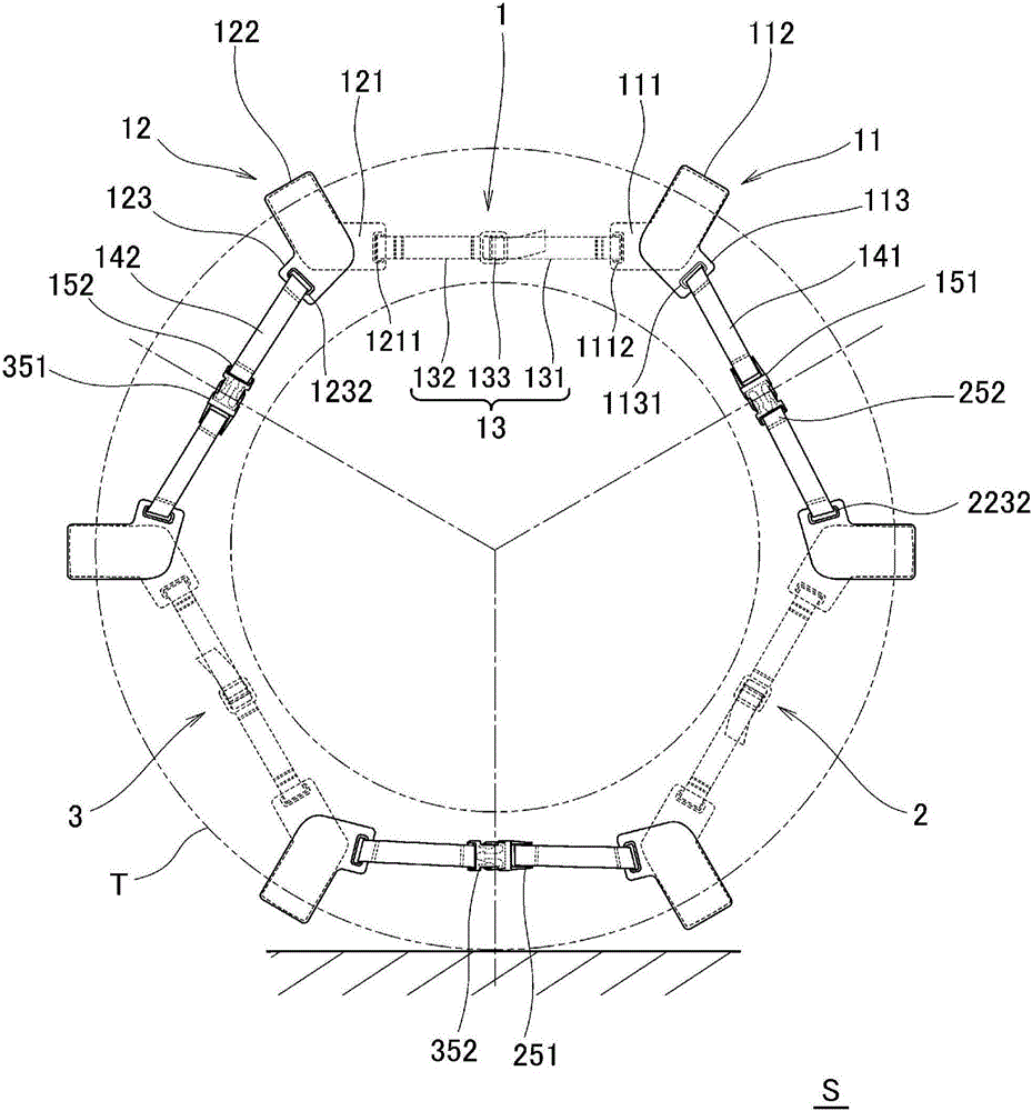
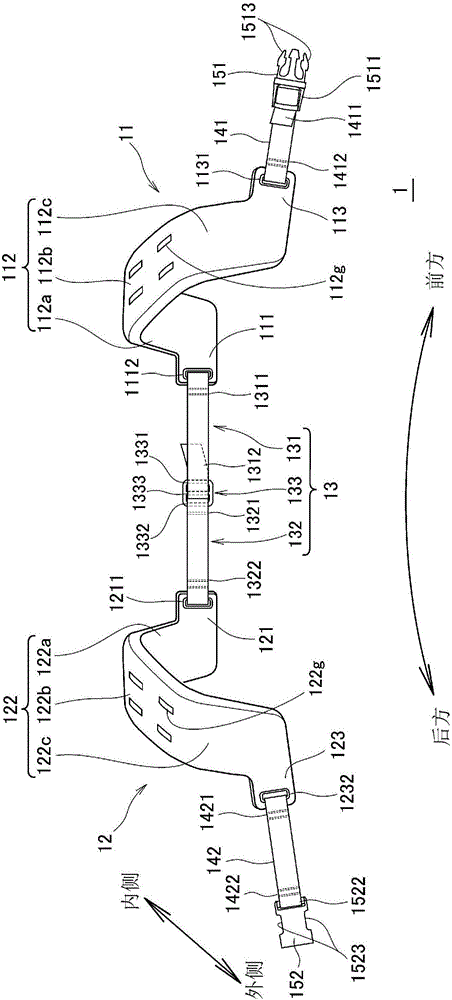
[0081] exist figure 1 A tire anti-skid device S (only referred to as "anti-skid device S") as an embodiment of the present invention is shown in a case where it is mounted on a tire T for a large vehicle. The anti-slip device S is composed of three unit units 1 , 2 , and 3 . The unit units 1, 2, and 3 have the same form respectively, and they are located on the decorative surface side of the wheel (not shown), that is, outside the tire T ( figure 1 The front side of the paper) are connected together in a detachable manner. Hereinafter, for the unit cell 1 as one of them, refer to figure 2 and as its partial enlargement image 3 It will be described in detail, and descriptions related to other unit cells will be omitted. In addition, the same reference numerals are attached to the same components, and their detailed descriptions are appropriately omitted.

[0082] "Unit Unit"

[0083] The unit unit 1 is composed of a first main body 11, a second main...

no. 2 example

[0106] exist Figure 4 The unit unit 5 is shown in FIG. It is formed by the inner belt-shaped connecting body 53 . In addition, the same reference numerals are assigned to the same components as in the case of the unit cell 1, and detailed descriptions are omitted. In addition, parts not described in detail are basically the same as in the case of the first embodiment. The above-mentioned situation is also the same in the following examples.

[0107] The first main body 51 and the second main body 52 of the unit unit 5 are composed of the unified main body 50 of the same form. Therefore, in the unit unit 5, there is no need to prepare two kinds of main bodies, and one kind of main body can be used in combination. Therefore, compared with the case of the unit unit 1 (2, 3), it is possible to realize manufacturing by reducing the number of parts. Cost and management cost reduction.

[0108] Specifically, the integrated main body 50 has a U-shaped portion 502 and four extend...

no. 3 example

[0113] exist Figure 5 A unit unit 7 is shown in , which is obtained by replacing the first body 11 of the unit unit 1 with a first body 71 and replacing the second body 12 with a second body 27 .

[0114] Both the first body 71 and the second body 72 of the unit unit 7 are constituted by the unified body 70 . This unified body 70 is formed in a simpler shape than the aforementioned unified body 50 . If the unit unit 7 composed of the integrated body 70 is used, not only the reduction of manufacturing cost and management cost can be further realized compared with the case of using the unit unit 1 (2, 3), but also compared with the case of using the unit unit 5 It is also possible to further reduce manufacturing costs and management costs.

[0115] Specifically, the integrated main body 70 is composed of an inner side part 701 which doubles as an inner extension part (an inner front extension part and an inner rear extension part), a cross part 702 which becomes a ground cont...


PUM


Abstract

Provided is an anti-slip device for a tire, the anti-slip device having significantly reduced cost. This anti-slip device (S) for a tire is provided with: a first body (11) having a first ground contact surface-like section (112b) which faces the tread of the tire and which extends in the circumferential direction, the first body (11) also having an inner rear connection section (1112) which faces the inner sidewall of the tire and which is provided behind the first ground contact surface-like section, the first body (11) further having an outer front connection section (1131) which faces the outer sidewall of the tire and which is provided in front of the first ground contact surface-like section; and a second body (12) disposed behind the first body, the second body (12) having a second ground contact surface-like section (122b) which faces the tread and which extends in the circumferential direction, the second body (12) also having an inner front connection section (1211) which faces the inner sidewall and which is provided in front of the second ground contact surface-like section, the second body (12) further having an outer rear connection section (1232) which faces the outer sidewall and which is provided behind the second ground contact surface-like section. The anti-slip device for a tire is characterized in that the inner rear connection section of the first body and the inner front connection section of the second body are connected.

Description

technical field [0001] The present invention relates to a tire anti-skid device (appropriately simply referred to as "anti-skid device") which is mounted on a tire of a motor vehicle and the like and which can prevent the tire from slipping on a snowy road or icy road, etc., and an anti-skid device used for the tire parts. Background technique [0002] When a motor vehicle or the like travels on a snowy road or an icy road, in order to avoid skidding or the like, the current countermeasures are to replace snow tires or install metal chains. However, snow tires cost more and have higher fuel consumption compared to summer tires. In addition, conventional metal chains are not easy to install, and especially in the case of large vehicles, the installation requires heavy physical labor. The inventors of the present invention have already proposed an epoch-making tire anti-skid device that can fundamentally solve such conventional problems, and it is described in the following ...

Claims


Application Information

Patent Timeline
Patent Type & Authority Applications(China)
IPC IPC(8): B60C27/20B60C27/06
CPCB60C27/02B60C27/0292B60C27/16B60C27/20
Inventor 榊原孝一
Owner KAGA CO LTD
Why Eureka
Try Eureka