A high-efficiency gluing device for flocking production and processing
What is Al technical title?
Al technical title is built by PatSnap Al team. It summarizes the technical point description of the patent document.
A gluing device and high-efficiency technology, which is applied to the surface coating liquid device, coating, equipment configuration for processing textile materials, etc., can solve the problems of uneven flocking, low flocking efficiency, and poor flocking effect. Achieve the effect of uniform flocking, high flocking efficiency and improved viscosity
Active Publication Date: 2018-12-14
河北博翼感光材料有限公司
View PDF5 Cites 0 Cited by
Summary
Abstract
Description
Claims
Application Information
AI Technical Summary
This helps you quickly interpret patents by identifying the three key elements:
Problems solved by technology
Method used
Benefits of technology
Problems solved by technology
[0007] In order to overcome the shortcomings of the existing flocking square glue-coating type flocking, uneven flocking, low flocking efficiency, and poor flocking effect, the technical problem to be solved by the present invention is to provide a uniform flocking, high flocking efficiency, High-efficiency gluing device for flocking production and processing with good flocking effect
Method used
Image
Click on the blue label to locate the original text in one second.
Reading with bidirectional positioning of images and text.
Examples
Embodiment 1
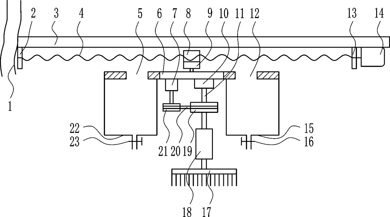
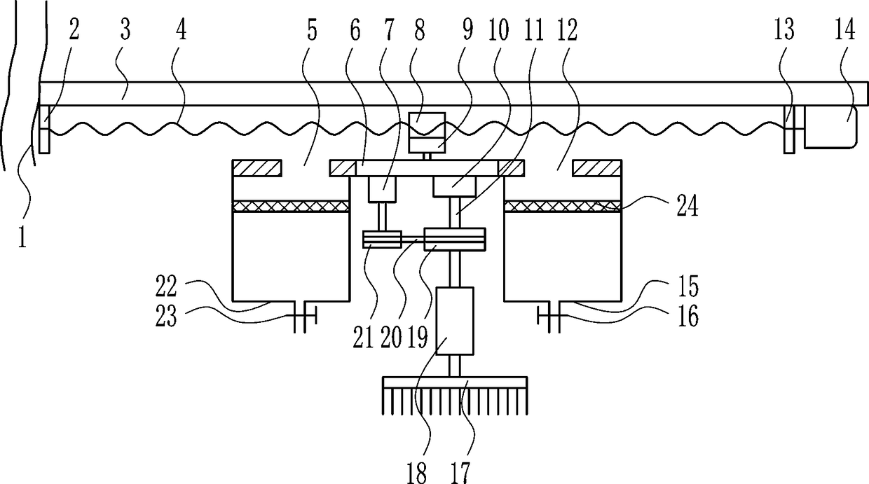
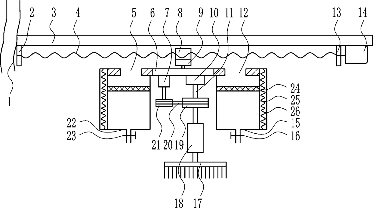
[0023] A high-efficiency gluing device for flocking production and processing, such as Figure 1-3 As shown, it includes hose 1, left bearing seat 2, top plate 3, screw rod 4, fixed plate 6, motor I7, nut 8, motor II9, bearing seat I10, rotating shaft 11, right bearing seat 13, motor III14, box Body Ⅰ15, electric control valve Ⅰ16, brush 17, electric push rod 18, large pulley 19, flat belt 20, small pulley 21, box body Ⅱ22 and electric control valve Ⅱ23, hose 1 is provided on the left side of the top plate 3, and the bottom of the top plate 3 From left to right, the left bearing seat 2, the right bearing seat 13 and the motor III14 are arranged in turn, and the screw rod 4 is installed between the left bearing seat 2 and the right bearing seat 13, and the right end of the screw rod 4 is connected with the motor III14, and the screw rod 4 is A nut 8 is installed, and the nut 8 cooperates with the screw rod 4. The bottom of the nut 8 is connected with a motor II9, and the bottom...
PUM
Abstract
The invention relates to a gluing device, in particular to an efficient gluing device for flocking production processing, and aims to solve the technical problem that an efficient gluing device for flocking production processing with uniform flocking, high flocking efficiency and good flocking effects is provided. To solve the technical problem, the invention provides the efficient gluing device for flocking production processing. The efficient gluing device comprises a hose, a left bearing seat, a top plate, a screw rod, a fixing plate, a motor I, a screw nut, a motor II, a bearing seat I, a rotating shaft, a right bearing seat, a motor III, a box body I, an electronic control valve I, a brush, an electronic push rod, a large belt pulley, a flat belt, a small belt pulley, a box body II and an electronic control valve II, wherein the hose is arranged on the left side of the top plate; the left bearing seat, the right bearing seat and the motor III are arranged from left to right in sequence at the bottom of the top plate; the screw rod is mounted between the left bearing seat and the right bearing seat. By adoption of the efficient gluing device, effects of uniform flocking, high flocking efficiency and good flocking effects are achieved.
Description
technical field [0001] The invention relates to a gluing device, in particular to a high-efficiency gluing device for flocking production and processing. Background technique [0002] The method of vertically fixing short fibers on an adhesive-coated substrate is called flocking. [0003] The principle of flocking is to make use of the physical characteristics of same-sex repulsion and opposite-sex attraction, so that the fluff is negatively charged, and the object to be flocked is placed under zero potential or grounding conditions, and the fluff is attracted by the plant body by the different potential, showing The vertical shape accelerates to fly to the object surface that needs flocking, and because the plant body is coated with adhesive, the fluff is just vertically stuck on the plant body. [0004] Gluing is the process of evenly applying glue to the surface of the fabric. There are four kinds of glue coating methods: scraping coating, roller coating, dip coating an...
Claims
Application Information
Patent Timeline
Application Date:The date an application was filed.
Publication Date:The date a patent or application was officially published.
First Publication Date:The earliest publication date of a patent with the same application number.
Issue Date:Publication date of the patent grant document.
PCT Entry Date:The Entry date of PCT National Phase.
Estimated Expiry Date:The statutory expiry date of a patent right according to the Patent Law, and it is the longest term of protection that the patent right can achieve without the termination of the patent right due to other reasons(Term extension factor has been taken into account ).
Invalid Date:Actual expiry date is based on effective date or publication date of legal transaction data of invalid patent.