
Self-adaption maximum power tracing control method of power generating set

A wind turbine, maximum power tracking technology, applied in the field of physics, can solve the problems of monotonous decrease of wind rotor output torque, monotonous increase of wind rotor output torque, and inability to directly measure the characteristics of speed and torque

Active Publication Date: 2016-08-31
SHANGHAI RO INTELLIGENT SYST
View PDF4 Cites 13 Cited by
  • Summary
  • Abstract
  • Description
  • Claims
  • Application Information

AI Technical Summary

Problems solved by technology

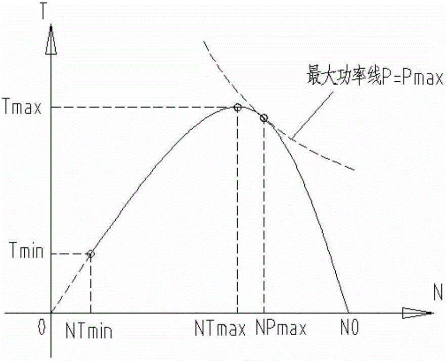
[0008] 5. Between NTmin and NTmax, the output torque of the wind rotor increases monotonously;
[0009] 6. Between NTmax and N0, the output torque of the wind rotor decreases monotonously;
In practice, there is no constant wind speed and wind direction in the natural environment, so the speed and torque characteristics under constant wind speed cannot be directly measured
In the wind tunnel environment, a constant wind speed can be artificially produced, but due to the influence of the size of the wind tunnel and the filling effect, larger vertical axis wind turbines cannot obtain accurate results through wind tunnel tests
[0014] The installation site of the same type of wind turbine is usually not fixed in one place, and its environment also changes with the seasons. Therefore, the speed-torque characteristic curve and optimal speed-torque tracking curve obtained in a specific site-specific environment are affected by different climates and terrains. The impact of wind turbines will change, so tracking a fixed optimal speed and torque tracking curve may cause the type of wind turbine to fail to generate maximum electrical energy under different test sites and different climatic conditions.

Method used


Image

  • Self-adaption maximum power tracing control method of power generating set
  • Self-adaption maximum power tracing control method of power generating set
  • Self-adaption maximum power tracing control method of power generating set

Examples


Embodiment Construction

[0098] The specific implementation of the self-adaptive maximum power tracking control method for wind power generating set of the present invention is introduced as follows:

[0099] Set the reference tip speed ratio and reference power coefficient of the wind turbine to be tested, and then determine the reference speed torque tracking curve and its deformation curve according to the reference tip speed ratio and reference power coefficient.

[0100] The reference tip speed ratio TSR and power coefficient CP of the wind turbine to be tested can be determined by the following three methods:

[0101] (1) Through numerical calculation, calculate the wind speed V, rotational speed N and output power P when the output power is maximum at the rated wind speed, so as to obtain TSR=N / 9.55*R / V and CP=P / (0.5×1.225A·V 3 );

[0102] (2) The optimal tip speed ratio and optimal power coefficient of the rated points of similar series of wind turbines are adopted.

[0103] (3) Set TSR=3.0 ...


PUM


Abstract

The invention provides a self-adaption maximum power tracing control method of a power generating set. First, the reference tip speed ratio and reference power coefficient of the to-be-tested power generating set are set, so that a reference rotate speed torque tracking curve and a deformation curve can be obtained according to the reference tip speed ratio and reference power coefficient. Then a section between a cut-in wind speed and a rated wind speed is divided into small sections. The power generating set runs according to the deformation curve corresponding to a deformation coefficient in a tracing manner. After each operation period, result data such as output power in the period are measured and subjected to statistical averaging. Therefore, during constant operation, the deformation coefficient is an optimization variable and the output power is an optimization object, the optimal deformation coefficient is sought through a method of optimization, so that the output power of the power generating set becomes the maximum. Finally, after long term operation of the power generating set, the optimal rotate speed torque tracking curve in the whole operation wind speed range can be obtained by connecting segments of the deformation curves determined according to deformation coefficients of each wind speed section.

Description

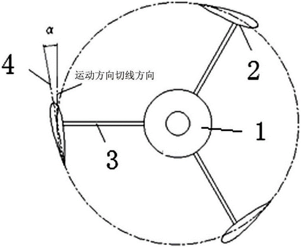
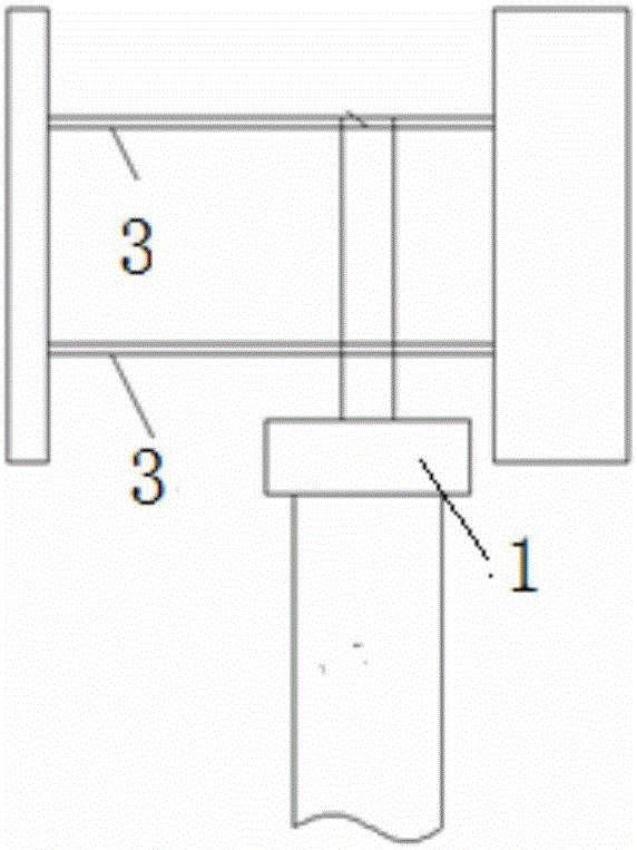
technical field [0001] The invention relates to the field of physics, in particular to wind power measurement and calculation, in particular to an adaptive maximum power tracking control method for wind power generating sets. Background technique [0002] The wind turbine can adopt the H-shaped Darrieux vertical shaft structure, and the structure of the wind rotor part is as follows: figure 1 and figure 2 shown. It adopts H-type fixed-wing straight blades 2, and the number of blades 2 is 2 to 4; the angle of attack between each blade 2 and the rotation direction is a fixed value α. The horizontal and transverse 3 connecting rods transform the aerodynamic force on the H-shaped straight blades into the torque acting on the rotor of the central generator of the wind turbine. The ratio of the radial projected area of ​​the blade 3 on the rotating swept surface of the blade geometric center to the entire swept surface is defined as the solidity SD, and the solidity SD of a ge...

Claims


Application Information

Patent Timeline
IPC IPC(8): F03D7/06
CPCF03D7/06F05B2270/1032F05B2270/1033F05B2270/32F05B2270/335Y02E10/74
Inventor 王建辉
Owner SHANGHAI RO INTELLIGENT SYST
Learn More