A self-shrinking automatic telescopic faucet
An automatic retractable and faucet technology, which is applied in the direction of water supply devices, engine components, pipes/pipe joints/fittings, etc., can solve the problems of automatic shrinkage and unsightly appearance, and achieve the effect of beautiful appearance, novel design and water leakage prevention
- Summary
- Abstract
- Description
- Claims
- Application Information
AI Technical Summary
Problems solved by technology
Method used
Image
Examples
Embodiment 1
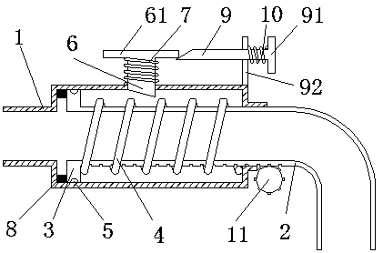
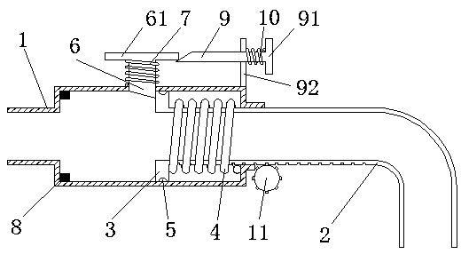
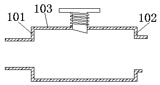
[0025] As a preferred embodiment of the present invention, with reference to the attached figure 1 to attach image 3 , this embodiment discloses a self-shrinking automatic telescopic faucet, this embodiment includes:
[0026] A self-shrinking automatic telescopic faucet, comprising a fixed pipe 1, a movable pipe 2, a fixed pin 6 and a pressure rod 9, the left end of the movable pipe 2 is arranged inside the fixed pipe 1, the right end is arranged outside the fixed pipe 1, and the movable pipe 2 The left end of the ring plate 3 is provided with a spring I4 between the ring plate 3 and the right wall 102 of the fixed tube 1; wall 103, and the fixed pin 6 is arranged between the annular plate 3 and the right wall 102 of the fixed tube 1, the end of the fixed pin 6 passing through the fixed tube 1 is an inclined plane, the left end of the inclined plane is flush with the inner wall of the fixed tube 1, and the right end It is arranged between the fixed pipe 1 and the movable pi...
Embodiment 2
[0028] As a preferred embodiment of the present invention, with reference to the attached figure 1 to attach image 3 , this embodiment discloses a self-shrinking automatic telescopic faucet, this embodiment includes:
[0029] A self-shrinking automatic telescopic faucet, comprising a fixed pipe 1, a movable pipe 2, a fixed pin 6 and a pressure rod 9, the left end of the movable pipe 2 is arranged inside the fixed pipe 1, the right end is arranged outside the fixed pipe 1, and the movable pipe 2 The left end of the ring plate 3 is provided with a spring I4 between the ring plate 3 and the right wall 102 of the fixed tube 1; wall 103, and the fixed pin 6 is arranged between the annular plate 3 and the right wall 102 of the fixed tube 1, the end of the fixed pin 6 passing through the fixed tube 1 is an inclined plane, the left end of the inclined plane is flush with the inner wall of the fixed tube 1, and the right end It is arranged between the fixed pipe 1 and the movable pi...
PUM
 Abstract
Description
Claims
Application Information
 - R&D
- Intellectual Property
- Life Sciences
- Materials
- Tech Scout
- Unparalleled Data Quality
- Higher Quality Content
- 60% Fewer Hallucinations
Browse by: Latest US Patents, China's latest patents, Technical Efficacy Thesaurus, Application Domain, Technology Topic, Popular Technical Reports.
© 2025 PatSnap. All rights reserved.Legal|Privacy policy|Modern Slavery Act Transparency Statement|Sitemap|About US| Contact US: help@patsnap.com


