Clamping mechanism of hub leak tester

A technology of clamping mechanism and leak testing machine, which is applied in the direction of detecting the appearance of fluid at the leakage point, using liquid/vacuum degree to measure the liquid tightness, etc., which can solve the problem of easy breakage of the tie rod 3, flying out of the hub, breakage of the tie rod, etc. problems, to achieve structural safety, ensure production safety, and avoid potential safety hazards

Inactive Publication Date: 2016-08-31
昆山六丰机械工业有限公司
View PDF9 Cites 0 Cited by
  • Summary
  • Abstract
  • Description
  • Claims
  • Application Information

AI Technical Summary

Problems solved by technology

[0004] The clamping mechanism of the hub leak tester of prior art, as figure 1 As shown, it includes two clamping devices arranged symmetrically and coaxially. The clamping device includes a main shaft 2, tie rods 3 respectively sleeved on both ends of the main shaft 2 and a chuck 1 for clamping the hub. The chuck 1 is arranged on the hub In the bracket, two oil cylinders 4 are connected to the two ends of the tie rod 3, and the two oil cylinders 4 and the main shaft 2 are arranged on the same side of the tie rod 3, and the other ends of the two oil cylinders 4 are respectively connected to the two ends of the hub bracket; the clamping mechanism When working, in the clamping device on one side, the oil cylinder drives the chuck to move, and the chuck in the clamping device on the other side makes relative motion to clamp the wheel hub. All the tension of the disc movement makes the tie rod 3 easy to break and slip, causing the tie rod to break suddenly during the leak test, and the chuck is loosened, causing the wheel hub to fly out and cause a safety accident

Method used


Image

  • Clamping mechanism of hub leak tester
  • Clamping mechanism of hub leak tester

Examples


Embodiment Construction

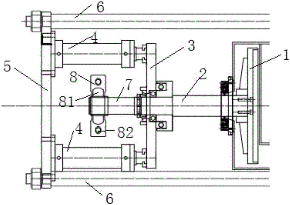
[0020] pass below figure 2 and specific embodiments to further illustrate the technical solution of the present invention.

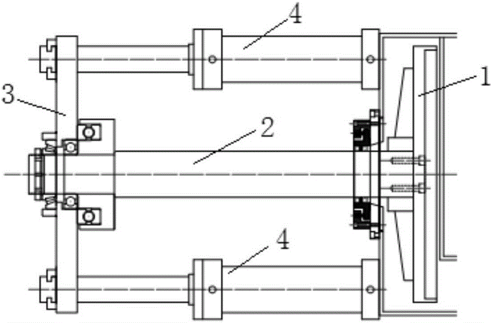
[0021] Such as figure 2 As shown, the clamping mechanism of the wheel hub leak tester of the present invention includes two clamping devices that are symmetrically and coaxially arranged. For the chuck 1 of the tight hub, the central axis of the tie rod 3 is perpendicular to the central axis of the main shaft 2, and the central axis of the chuck 1 is parallel to the central axis of the main shaft 2; The main shaft 2 is respectively arranged on both sides of the pull rod 3, and a fixed plate 5 is connected between the ends of the two oil cylinders 4, and the two ends of the fixed plate 5 are respectively connected with the fixed shaft 6 of the hub leak tester, and the fixed shaft 6 The central axis of is parallel to the central axis of main shaft 2. When the clamping mechanism of the hub leak testing machine of the present invention is in operation, ...


PUM


Abstract

The invention discloses a clamping mechanism of a hub leak tester. The clamping mechanism comprises two clamping devices which are symmetrically and coaxially arranged, wherein each clamping device comprises a main shaft, and a pull rod and a chuck which sleeve both ends of the main shaft; the chuck is used for clamping a hub; the central axis of the pull rod is perpendicular to the central axis of the main shaft; the central axis of the chuck is parallel to the central axis of the main shaft; both ends of the pull rod are connected with two oil cylinders, the two oil cylinders and the main shaft are arranged on two sides of the pull rod separately, and a fixed plate is connected between the tail end parts of the two oil cylinders; and two ends of the fixed plate are connected with a fixed shaft of the hub leak tester, and the central axis of the fixed plate is parallel to the central axis of the main shaft. The clamping mechanism of the hub leak tester is safe in structure, reduces equipment failure rate, and ensures production safety.

Description

technical field [0001] The invention belongs to the technical field of workpiece airtightness testing, and in particular relates to a clamping mechanism of a hub leak testing machine. Background technique [0002] Leak tester, also known as leak tester and leak tester, is mainly used in automobiles, internal combustion engines, motorcycles, compressors and other industries. It is an important equipment to detect the leakage status of its parts and ensure product quality. The hub is the skeleton of the car wheel, which is formed by die-casting aluminum alloy and cannot leak air. In order to detect whether there is leakage in the manufacturing process of the wheel hub, and to ensure that the tire will not cause accidents due to the leakage of the wheel hub during use, it is necessary to perform a pressurized leak test on the product. In order to clearly find defects such as sand holes and cracks that may exist in the wheel hub, the wheel hub leak tester is used in the prior a...

Claims


Application Information

Patent Timeline
Patent Type & Authority Applications(China)
IPC IPC(8): G01M3/06
CPCG01M3/06
Inventor 宗绪惠魏授桐朱正刚
Owner 昆山六丰机械工业有限公司
Why Eureka
Try Eureka