Plane rotation construction technique for steel truss girder for existing bridge spanning construction

A technology of bridge construction and construction technology, which is applied in the direction of bridges, bridge construction, erection/assembly of bridges, etc., and can solve problems such as inability to carry out normal construction and large traffic interference on existing lines

Active Publication Date: 2012-10-17
NO 1 ENG LIMITED OF CR20G
View PDF5 Cites 14 Cited by
  • Summary
  • Abstract
  • Description
  • Claims
  • Application Information

AI Technical Summary

Problems solved by technology

[0004] The technical problem to be solved by the present invention is to provide a steel truss girder planar swivel construction technology for bridge construction spanning existing lines in view of the deficiencies in the above-mentioned prior art. The construction process steps are simple, convenient, fast and safe Reliable, with little

Method used


Image

  • Plane rotation construction technique for steel truss girder for existing bridge spanning construction
  • Plane rotation construction technique for steel truss girder for existing bridge spanning construction
  • Plane rotation construction technique for steel truss girder for existing bridge spanning construction

Examples


Embodiment Construction

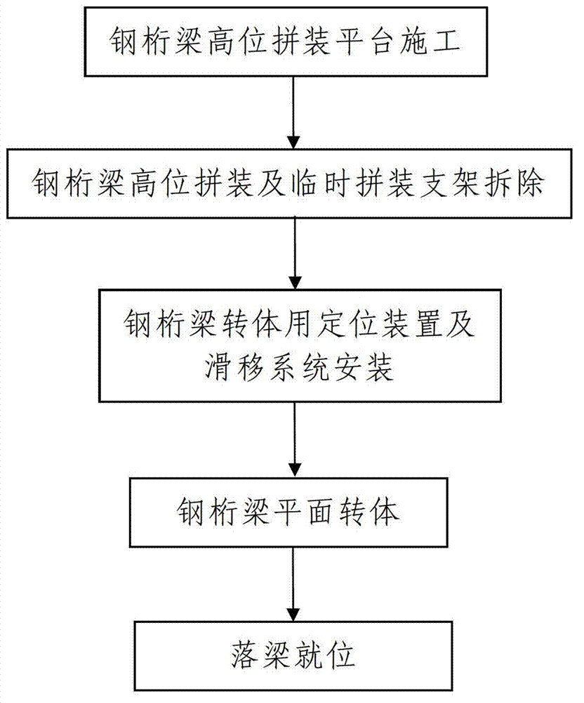
[0078] Such as figure 1 A steel truss girder planar swivel construction technology for bridge construction spanning existing lines is shown, including the following steps:

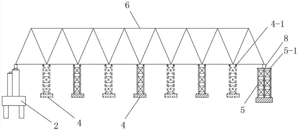
[0079] Step 1. Construction of steel truss girder high-level assembled platform: combined figure 2 and image 3 , erecting the steel truss girder high-level assembly platform for assembling the steel truss girder 6 .

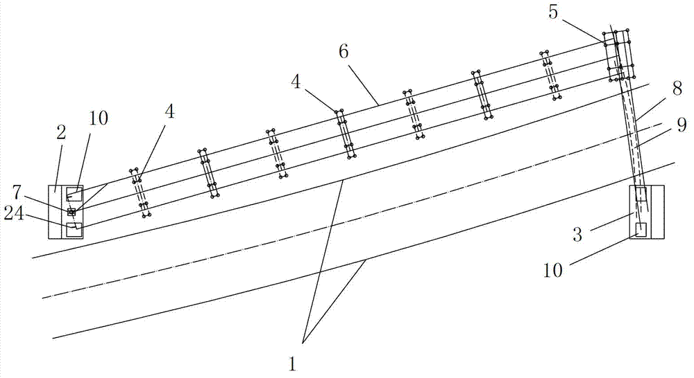
[0080] Such as figure 1 The bridge constructed by the steel truss girder plane swivel construction process shown crosses the existing line 1 and obliquely intersects with the existing line 1. The existing line 1 is a double-track railway line, and the main girders of the constructed bridge are at the front and rear ends Steel truss girders 6 respectively supported on permanent pier 1 2 and permanent pier 2 3, see figure 2 The steel truss girder 6 is assembled from a plurality of steel truss girder segments, the permanent pier 2 and the permanent pier 2 3 are reinforced concrete piers, ...


PUM


Abstract

The invention discloses a plane rotation construction technique for a steel truss girder for existing bridge spanning construction. A main girder of the constructed bridge is a steel truss girder spanning the existing bridge and obliquely crossing with the existing bridge; the technique comprises the following steps: firstly, constructing a high-altitude steel truss girder assembling platform which comprises a temporary buttress and a plurality of temporarily assembling brackets; secondly, assembling the steel truss girder at high altitude and removing the temporarily assembling brackets; thirdly, installing a steel truss girder rotation positioning device and a slippage system; before rotating the steel truss steel, firstly installing the steel truss girder rotation positioning device and the slippage system; fourthly, conducting plane rotation on the steel truss girder; and fifthly, dropping the girder in place. The construction technique is simple in steps, convenient to construct, fast to construct, safe and reliable in construction process and less in interference on the existing bridge, and can effectively solve the problems that the construction field is limited, the construction can not be normally conducted, the travelling interference on the existing bridge is large, the construction risk and hidden hazard are large and the like in construction with the existing in-situ falsework method and the dragging method.

Description

technical field [0001] The invention belongs to the technical field of bridge swivel construction, and in particular relates to a steel truss girder planar swivel construction technology for bridge construction across existing lines. Background technique [0002] Nowadays, there are many bridge construction projects spanning existing lines, and the bridges spanning existing lines include various types of bridges crossing existing railway operating lines and connecting road lines. Among them, for the construction of steel truss girders spanning existing lines, the actual construction of bridges on existing lines is not only complicated and difficult, but also likely to have a greater impact on the operation of the existing lines. At present, when constructing the steel truss girder spanning the existing line, the dragging method or the in-situ scaffolding method are usually used for erection. Among them, the dragging method refers to erecting a temporary support around the c...

Claims


Application Information

Patent Timeline
IPC IPC(8): E01D21/08
Inventor 刘建新杜越张林唐培文张照龙严朝锋王永丽王刚张永鸿赵朝阳仲维玲朱红桃
Owner NO 1 ENG LIMITED OF CR20G
Why Eureka
Try Eureka