Circular whole loop tunnel structure test device

A technology of tunnel structure and test device, which is applied to the testing, measuring device, instrument and other directions of machine/structural components, can solve the problems of reduced cost of test device, limited versatility and high cost, and achieves excellent versatility, The effect of easy installation or removal and cost reduction

Inactive Publication Date: 2016-08-31
TONGJI UNIV +1
View PDF4 Cites 10 Cited by
  • Summary
  • Abstract
  • Description
  • Claims
  • Application Information

AI Technical Summary

Problems solved by technology

[0003] In order to overcome the shortcomings of high cost and limited versatility of the circular full-ring tunnel using the reaction force frame device for loading, the present invention provides a test device for the circular full-ring tunnel structure. The test device is composed of a tie rod and a loading beam The symmetrical tension self-balancing system is used for loading, the cost of the test device is greatly reduced, and by adjusting the position of the nut on the tie rod, it can be applied to the test loading of circular full-ring tunnels with various diameters

Method used


Image

  • Circular whole loop tunnel structure test device
  • Circular whole loop tunnel structure test device
  • Circular whole loop tunnel structure test device

Examples


Embodiment Construction

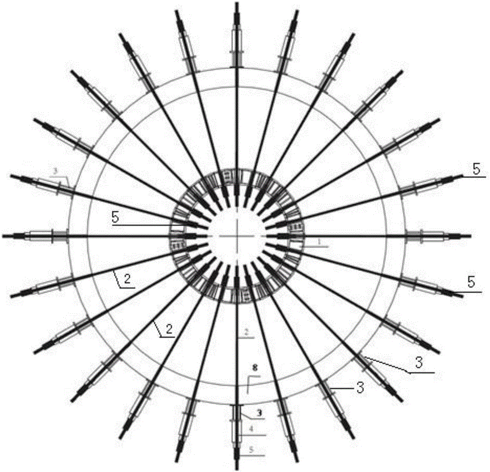
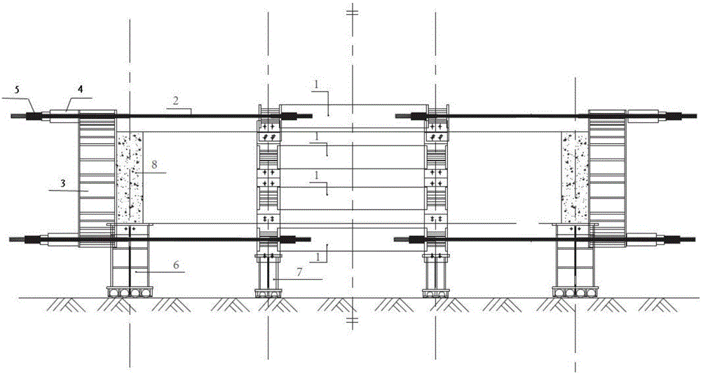
[0018] The top view of the test device is as figure 1 shown in the structure, image 3 just for understanding figure 2 The positional relationship between ring beams and segments.

[0019] In this embodiment, a test device for a circular full-ring tunnel structure includes a ring beam module, a circular full-ring tunnel segment 8, 48 tie rods 2, 24 tension beams 3, 48 jacks 4, and nuts 5 , sliding support A, sliding support B, bolt splicing plate 9,

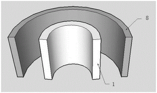
[0020] The ring beam module and segment 8 are two concentric circle structures, the ring beam module is on the inner side, and the circular full-ring tunnel segment 8 is on the outside. The circular full-ring tunnel segment 8 is placed on the sliding support A, The ring beam module is placed on the sliding support B,

[0021] The ring beam module described in this embodiment is composed of upper and lower four-layer ring beam units 1 superimposed, and the upper and lower adjacent ring beam units 1 are connected by bolt splic...


PUM


Abstract

A circular whole loop tunnel structure test device is disclosed. A symmetric straining self-balance system formed by pull rods and loading beams is used for a loading purpose, and production cost is substantially reduced; by adjusting a position of a screw nut on the pull rod, the test device can be suitable for test loading of a circular whole loop tunnel of all diameter sizes. The circular whole loop tunnel structure test device comprises an annular beam module, a circular whole loop tunnel duct segment, a number of pull rod groups, a number of straining beams, a jack, a sliding support seat A and a sliding support seat B, wherein the annular beam module and the duct segment are two concentric circular structures, the annular beam module is arrange at an inner side while the circular whole loop tunnel duct segment is arranged at an outer side, the circular whole loop tunnel duct segment is placed on the sliding support seat A, the annular beam module is placed on a sliding support seat B, the straining beams are closely attached to the outer side of the duct segment and are uniformly arranged into a cycle along the circular whole loop tunnel duct segment or at other angles, the pull rod groups are connected with the straining beams outside the duct segment and an inner side of the annular beam module, the jack is mounted on the pull rod groups in a penetrated manner at an outer peripheral side, the jack is locked on the outer sides of the straining beams, and the inner side of the annular beam module is fixed.

Description

technical field [0001] The invention relates to a test device for a circular full-ring tunnel structure, in particular to a test loading device for a symmetrical tension self-balancing system composed of tie rods and loading beams. Background technique [0002] The circular full-ring tunnel mainly bears radial loads. If the traditional reaction frame loading device is used, a reaction frame specially designed for loading according to the contour of the full-ring tunnel will be required, and the cost of the reaction frame is usually very expensive, and Versatility is limited by the size of the circular tunnel diameter. Contents of the invention [0003] In order to overcome the shortcomings of high cost and limited versatility of the circular full-ring tunnel using the reaction force frame device for loading, the present invention provides a test device for the circular full-ring tunnel structure, which is composed of a tie rod and a loading beam The symmetrical tension se...

Claims


Application Information

Patent Timeline
Patent Type & Authority Applications(China)
IPC IPC(8): G01M99/00
CPCG01M99/007
Inventor 蒋首超柳献林维春文见朱瑶宏林平夏汉庸董子博
Owner TONGJI UNIV
Why Eureka
Try Eureka