A reluctance disc motor

A disc motor and reluctance technology, applied to synchronous motors with stationary armatures and rotating magnets, etc., to achieve the effects of short axial size, high motor power density, and simple rotor structure

Active Publication Date: 2018-05-25
SHANDONG UNIV OF TECH
View PDF4 Cites 0 Cited by
  • Summary
  • Abstract
  • Description
  • Claims
  • Application Information

AI Technical Summary

Problems solved by technology

[0007] At present, the applicant has not retrieved a reluctance type disc motor involved in the present invention through searching at home and abroad. The working principle of the motor, which is different from the traditional motor principle

Method used


Image

  • A reluctance disc motor
  • A reluctance disc motor
  • A reluctance disc motor

Examples


Embodiment Construction

[0028] The invention will be described in further detail below in conjunction with the accompanying drawings.

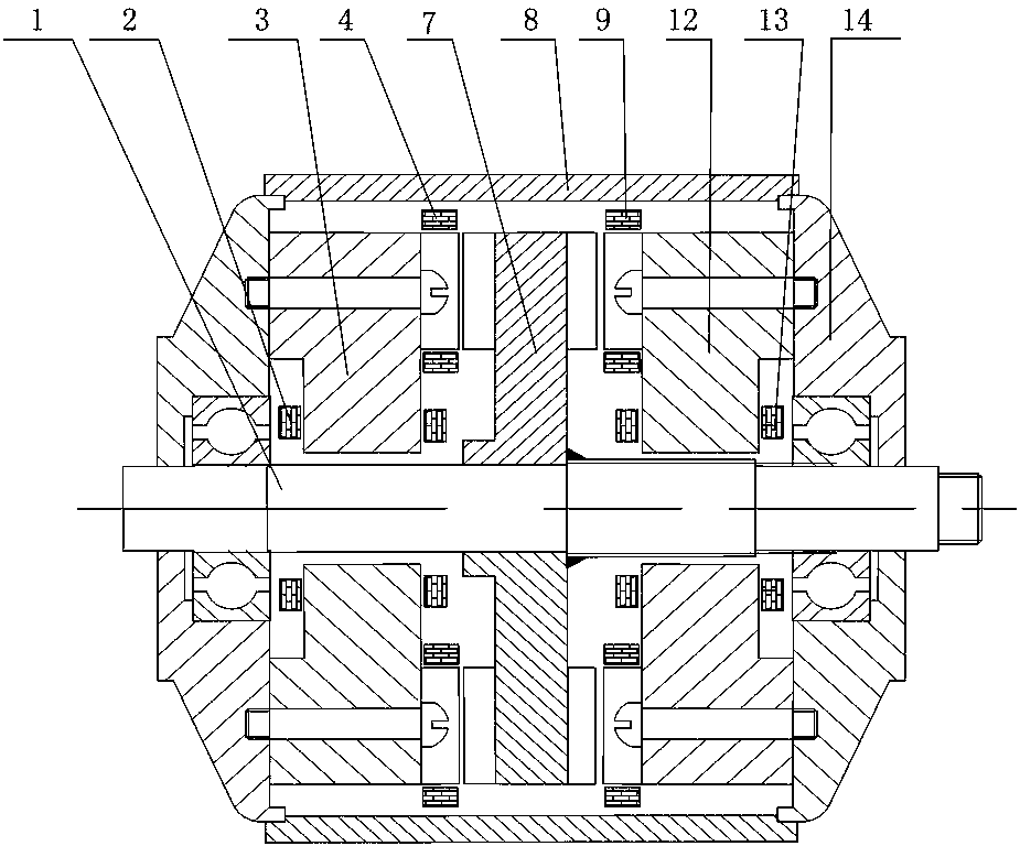
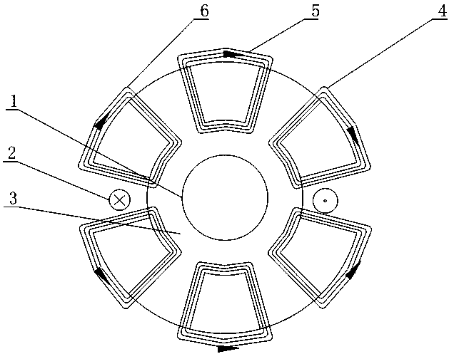
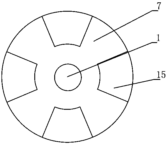
[0029] figure 1 It is a longitudinal sectional view of a reluctance disc motor of the present invention. A reluctance type disc motor shown consists of a shaft (1), a first excitation coil (2), a first stator core (3), a first armature coil, a rotor core (7), and a casing (8 ), the second armature coil (9), the second stator core (12), the second field winding (13) and the end cover (14). The rotor core (7) is disc-shaped and fixed on the shaft (1). The rotor core (7) has 2N circular fan-shaped raised rotor poles on both end faces of the disc; the first stator core ( 3), the axes of the second stator core (12) and the rotor core (7) are the same, the first stator core (3) and the second stator core (12) are respectively located on both sides of the rotor core (7), the first stator On the side opposite to the rotor core (7) of the sub-core (3) there are 3N ring sec...


PUM


Abstract

The invention proposes a reluctance type disc motor, which includes a shaft, a first excitation coil, a first stator core, a first armature coil, a rotor core, a casing, a second armature coil, a second stator core, a first Two field windings and end caps; the first stator core has a groove every three first stator poles, and the first field coil is embedded in the groove, and the first field coil is wound around the three first stator poles And the winding directions of the adjacent first excitation coils are opposite; the second stator core has a groove every three second stator poles, and the second excitation coil is embedded in the groove, and the second excitation coil is wound around three second stator poles. The stator poles are wound and the adjacent second excitation coils are wound in the opposite direction; each first stator pole is wound with a first armature coil, and each second stator pole is wound with a second armature coil The armature coils of the same phase can be connected in series or in parallel to form a phase winding. The reluctance disc motor of the present invention can effectively utilize the advantage of relatively high efficiency of the switched reluctance motor, and also effectively utilize the advantages of small size and high reliability of the electrically excited disc motor.

Description

technical field [0001] The invention relates to a reluctance disc motor, which belongs to the technical field of special motors. Background technique [0002] Permanent magnet motors, especially miniature permanent magnet DC motors, have been widely used due to their simple structure and process and light weight. However, since rare earth permanent magnets are still relatively expensive at present, the cost of rare earth permanent magnet motors is generally higher than that of electric excitation motors, which needs to be compensated by its high performance and reduced operating costs. Therefore, permanent magnet motors are only suitable for small power applications. For high-power special motors, electric excitation motors are more suitable. [0003] With the gradual expansion of the application range of motors, motor generators have more and more extensive application values. A motor generator is a motor that has both the functions of a generator and a motor. For examp...

Claims


Application Information

Patent Timeline
Patent Type & Authority Patents(China)
IPC IPC(8): H02K21/24
CPCH02K21/24
Inventor 肖东史立伟郭盈志张学义巩合聪刘从臻徐晓明
Owner SHANDONG UNIV OF TECH
Why Eureka
Try Eureka