
Overload preventing transmission device

A transmission device and transmission shaft technology, applied in electromechanical devices, electric components, electric brakes/clutches, etc., can solve problems such as motor burnout, and achieve the effect of preventing overloading

Inactive Publication Date: 2016-08-31
BENGBU ZHIDA TECH CONSULTING CO LTD
View PDF5 Cites 6 Cited by
  • Summary
  • Abstract
  • Description
  • Claims
  • Application Information

AI Technical Summary

Problems solved by technology

[0002] At present, most of the connecting devices used to connect the driving shaft and the transmission shaft are bolted, so that the transmission speed of the main shaft is the same as that of the auxiliary shaft. However, since the auxiliary shaft is connected to the device that needs to be driven, when it needs to be driven When the device is heavy, the main shaft needs to provide greater transmission force at this time. When the transmission force at this time is greater than the rated output of the motor, it is likely that the motor will burn out.

Method used


Image

  • Overload preventing transmission device

Examples


Embodiment Construction

[0012] The following will clearly and completely describe the technical solutions in the embodiments of the present invention with reference to the accompanying drawings in the embodiments of the present invention. Obviously, the described embodiments are only some, not all, embodiments of the present invention. Based on the embodiments of the present invention, all other embodiments obtained by persons of ordinary skill in the art without making creative efforts belong to the protection scope of the present invention.

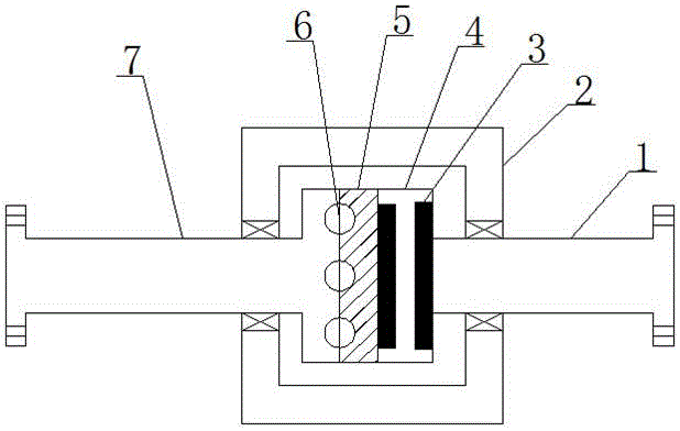
[0013] see figure 1 , the present invention provides a technical solution: an anti-overload transmission device, including a first transmission shaft 1, a cylindrical shell 2, a powerful permanent magnet 3, a hollow chamber 4, a circular baffle 5, balls 6 and a second transmission shaft 7. The first transmission shaft 1 and the second transmission shaft 7 are connected to the cylindrical casing 2 through bearings, and one end of the first transmission shaft 1 ...


PUM


Abstract

The invention discloses an overload preventing transmission device comprising a first transmission shaft, a cylindrical shell, strong permanent magnets, a hollow chamber, a circular baffle plate, rolling balls and a second transmission shaft. The first transmission shaft and the second transmission shaft are connected with the cylindrical shell through a bearing. One end of the first transmission shaft is provided with the hollow chamber. One strong permanent magnet is arranged in the hollow chamber. One end of the hollow chamber is sleeved by the circular baffle plate. One end of the circular baffle plate is provided with one circular baffle plate. The other end of the circular baffle plate is connected with one end of the second transmission shaft through the rolling balls. According to the overload preventing transmission device, the rolling balls are separated from grooves when rotating force from the second transmission shaft is greater than the effect of repulsive force between the strong permanent magnets through the effect of the repulsive force between the strong permanent magnets so that the second transmission shaft is enabled to stop rotating, and then the overload phenomenon of a motor can be prevented.

Description

technical field [0001] The invention relates to the technical field of transmission devices, in particular to an anti-overload transmission device. Background technique [0002] At present, most of the connecting devices used to connect the driving shaft and the transmission shaft are bolted, so that the transmission speed of the main shaft is the same as that of the auxiliary shaft. However, since the auxiliary shaft is connected to the device that needs to be driven, when the required When the device is heavy, the main shaft needs to provide greater transmission force. When the transmission force is greater than the rated output of the motor, the motor may burn out. Contents of the invention [0003] The purpose of the present invention is to provide an anti-overloading transmission device to solve the problems raised in the above-mentioned background technology. [0004] In order to achieve the above object, the present invention provides the following technical soluti...

Claims


Application Information

Patent Timeline
Patent Type & Authority Applications(China)
IPC IPC(8): H02K49/10
CPCH02K49/108
Inventor 许振亮
Owner BENGBU ZHIDA TECH CONSULTING CO LTD
Learn More