Ventilation damper system and method

A damper and damper technology, applied in the field of ventilation damper systems and methods, can solve the problems of generating extra noise, increasing noise, etc.

Active Publication Date: 2016-08-31
BROAN NUTONE
View PDF7 Cites 0 Cited by
  • Summary
  • Abstract
  • Description
  • Claims
  • Application Information

AI Technical Summary

Problems solved by technology

In particular, the shape of the backstop damper can reflect sound through the ventilation assembly housing, thereby increasing the noi

Method used


Image

  • Ventilation damper system and method
  • Ventilation damper system and method
  • Ventilation damper system and method

Examples


Embodiment Construction

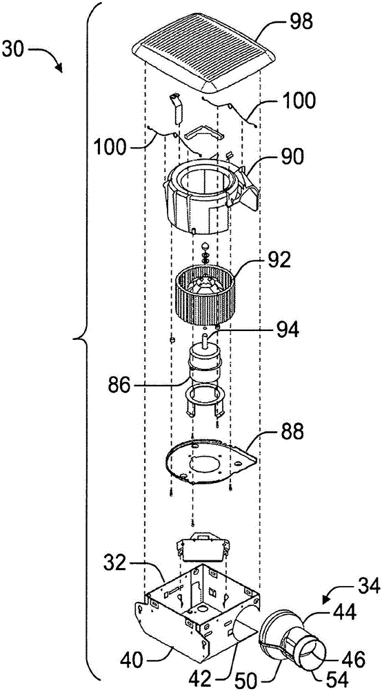
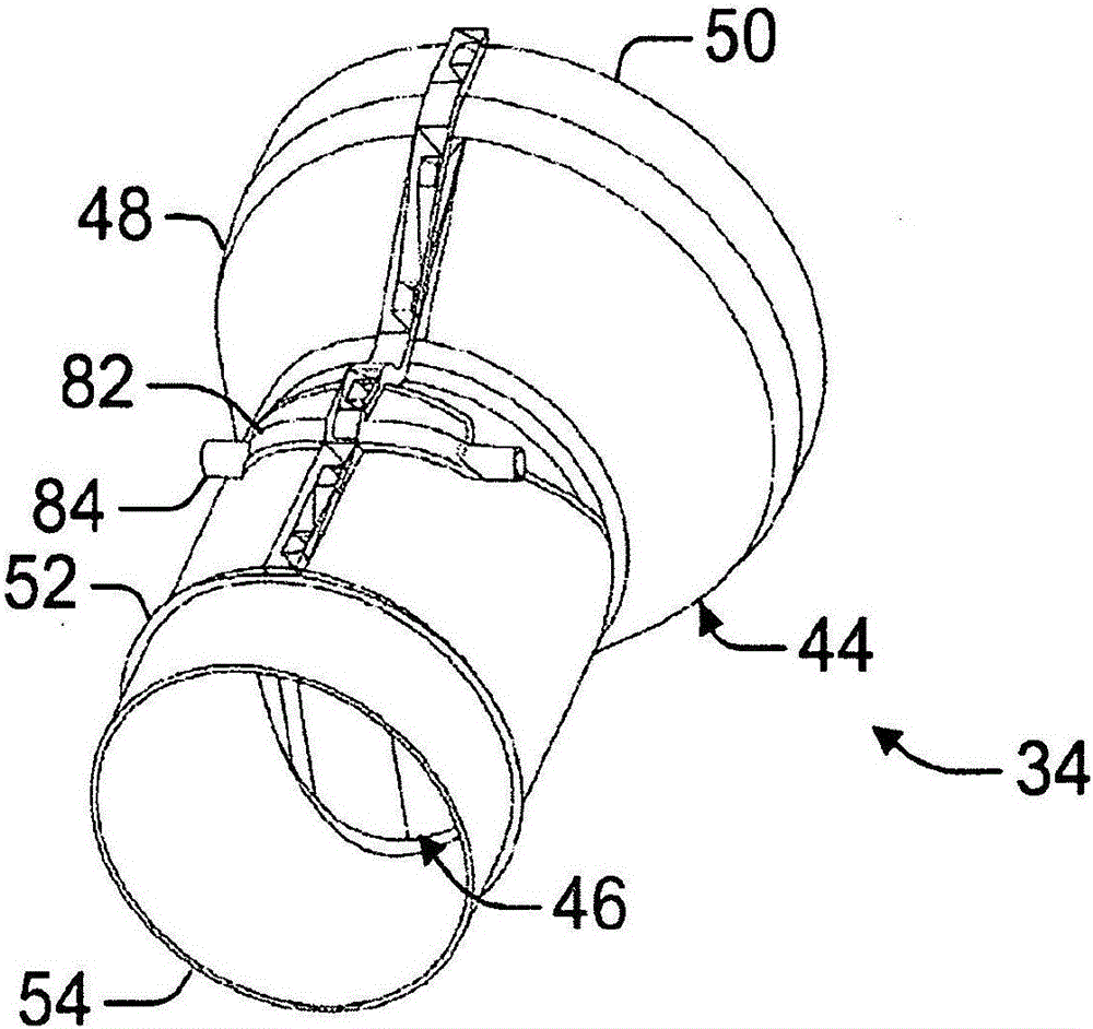
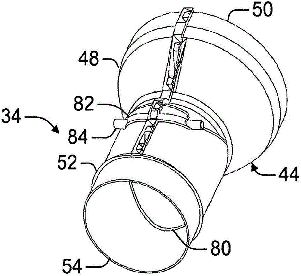
[0047] like figure 1 As shown, a ventilation assembly 30 according to one example can include a main housing 32 , a damper assembly 34 and a fan assembly 36 . The main housing 32 can include a housing wall 38 defining an interior space and can include at least an inlet 40 and an outlet 42 . Fan assembly 36 is positionable within the interior space and is operable to generate an input airflow through inlet 40 and an output airflow through outlet 42 . like Figure 4A to Figure 4C As shown, the damper assembly 34 can include a main body 44 and a damper door 46 that is rotatable within the main body 44 between at least an open position and a closed position. The body 44 can be positioned at the outlet 42 and is formed in the shape of a tube with an opening for directing the output airflow out of the outlet 42 . In the open position, the damper 46 is rotated to position the damper 46 within the body 44 to allow airflow through the opening. In the closed position, the damper 46 ...


PUM


Abstract

A damper assembly is disclosed and includes a main body defining a continuous fluid path extending between a first opening and a second opening, and a damper door rotatable within the main body to control the flow of fluid through the main body. The main body includes an engagement edge extending circumferentially on an inner surface of the main body. The damper door can be rotated relative to the main body to sealingly engage an outer edge of the damper door with the engagement edge. The engagement edge of the main body can be oriented on the inner surface such that the surface area of the outer edge such that engagement of the engagement edge gradually increases as the damper door is rotated to seal the damper door to the main body.

Description

[0001] priority statement [0002] This patent application claims "VENTILATION DAMPER SYSTEM AND METHOD" filed November 18, 2013 by Robert G. Penlesky et al. SYSTEMAND METHOD)" and application number 61 / 935,754 (Attorney Docket No. 5978.202PV2) filed February 4, 2014 by Robert G. Penlesky et al. and entitled "Ventilation Damper System and methods", which are hereby incorporated by reference in their entirety. technical field [0003] This document relates primarily, but not exclusively, to ventilation systems with dampers and ventilation damper systems. Background technique [0004] Ventilation exhaust fans, such as those commonly installed in bathrooms, draw air from within a space and send the exhaust air out, for example, by sending the exhaust air through a building's gabled roof or vents in the roof. another location. The exhaust fan can include a rotary fan wheel with a plurality of blades that rotate within the housing to draw airflow inward from the space through ...

Claims


Application Information

Patent Timeline
IPC IPC(8): F24F13/10
CPCF24F2007/002F24F7/007F24F13/10
Inventor R·G·彭勒斯基K·J·乔纳斯C·S·杰卡克
Owner BROAN NUTONE
Why Eureka
Try Eureka