Automatic temperature control ventilation cabinet

A fume hood and cabinet technology, applied in the field of laboratory equipment, can solve problems such as hidden safety hazards, temperature rise, incomplete discharge of toxic and harmful gases, etc., and achieve the effect of ensuring safety and precise control

Active Publication Date: 2016-09-07
ANHUI YUAN LAB EQUIP
View PDF5 Cites 3 Cited by
  • Summary
  • Abstract
  • Description
  • Claims
  • Application Information

AI Technical Summary

Problems solved by technology

[0002] The fume hood is an indispensable part of the laboratory design. In order to ensure that the laboratory staff do not inhale some toxic and harmful chemicals and organisms, the laboratory should maintain good ventilation, but in the actual operation process, the experiment Not only will some toxic and harmful gases be produced, but some chemicals need to be heated or even use an open flame, causing the temperature in the fume hood to rise continuously; but most of the existing fume hoods only have one ventilation device, and at the same time, the toxic and harmful gases in the fume hood To discharge and ventilate the temperature in the fume hood. Due to the limitation of the ventilation device, this design may have the problem of incomplete discharge of toxic and harmful gases, which will pose a threat to the health of the experimental operators and cause damage to the laboratory environment. impact; there may also be the disadvantage of not being able to reduce the temperature in the fume hood in time, so that the temperature in the fume hood continues to rise, there are potential safety hazards, and the safety of the experimental operation cannot be guaranteed; Take countermeasures against toxic and harmful gases and the temperature in the fume hood to fully ensure the safety of experimental operations

Method used


Image

  • Automatic temperature control ventilation cabinet
  • Automatic temperature control ventilation cabinet

Examples


Embodiment Construction

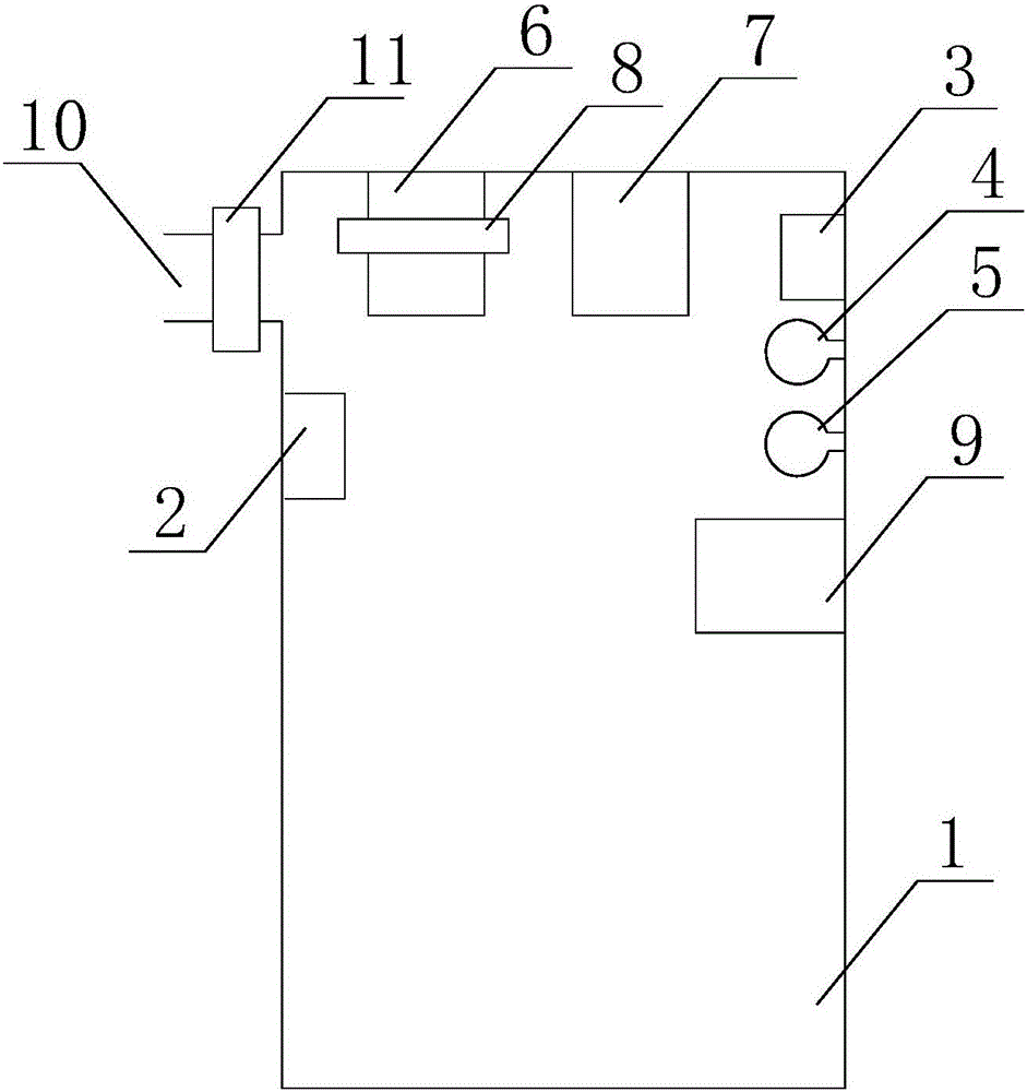
[0020] like figure 1 , figure 2 as shown, figure 1 , figure 2 It is an automatic temperature control fume hood proposed by the present invention.

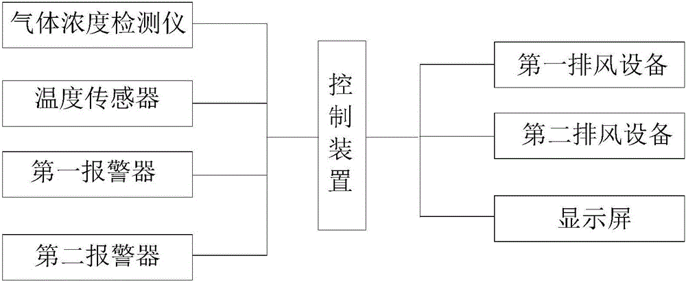
[0021] refer to figure 1 , figure 2 , the automatic temperature control fume hood that the present invention proposes, comprises: cabinet body 1, exhaust device, warning device and control device;

[0022] The inside of the cabinet 1 is provided with a gas concentration detector 2 for detecting the concentration of toxic and harmful gases in the cabinet 1; the inside of the cabinet 1 is provided with a temperature sensor 3 for detecting the internal temperature of the cabinet 1;

[0023] The cabinet body 1 is provided with an air outlet 10, and the air outlet 10 is provided with a filter device 11, and the filter device 11 includes: an acid absorption layer, an alkali absorption layer, an activated carbon absorption layer and a drying layer. It is used to absorb and discharge the toxic and harmful gas generated in the cabi...


PUM


Abstract

The invention discloses an automatic temperature control ventilation cabinet. The automatic temperature control ventilation cabinet comprises a cabinet body, an exhaust device, a warning device and a control device; a gas concentration detector for detecting the concentration of poisonous and harmful gas and a temperature sensor for detecting the internal temperature of the cabinet body are arranged on the inner side of the cabinet body; the warning device works according to instructions of the control device; the exhaust device includes first exhaust equipment and second exhaust equipment; the first exhaust equipment is provided with an electromagnetic valve, and includes three exhaust modes; the electromagnetic valve is different in openness under different exhaust modes; the second exhaust equipment includes three exhaust grades, and is different in working power under different exhaust grades; the control device dynamically controls the first exhaust equipment to work in different exhaust modes according to different gas concentration values in the cabinet body; and the control device dynamically controls the second exhaust equipment to work in different exhaust grades according to the temperature in the cabinet body.

Description

technical field [0001] The invention relates to the technical field of laboratory equipment, in particular to an automatic temperature control fume hood. Background technique [0002] The fume hood is an indispensable part of the laboratory design. In order to ensure that the laboratory staff do not inhale some toxic and harmful chemicals and organisms, the laboratory should maintain good ventilation, but in the actual operation process, the experiment Not only will some toxic and harmful gases be produced, but some chemicals need to be heated or even use an open flame, causing the temperature in the fume hood to rise continuously; but most of the existing fume hoods only have one ventilation device, and at the same time, the toxic and harmful gases in the fume hood To discharge and ventilate the temperature in the fume hood. Due to the limitation of the ventilation device, this design may have the problem of incomplete discharge of toxic and harmful gases, which will pose a...

Claims


Application Information

Patent Timeline
IPC IPC(8): B08B15/02
CPCB08B15/023
Inventor 张然袁巍王跃
Owner ANHUI YUAN LAB EQUIP
Why Eureka
Try Eureka