Deburring tool for deburring of nonround contours of workpieces

A workpiece contour and deburring technology, applied in the field of deburring tools, can solve the problem of unsuitable deburring tools

Inactive Publication Date: 2016-09-07
HEULE WERKZEUG
View PDF7 Cites 6 Cited by
  • Summary
  • Abstract
  • Description
  • Claims
  • Application Information

AI Technical Summary

Problems solved by technology

Such deburring tools are not suitable for the deburring of non-circular grooves or non-circular borehole diameters in the radial direction of the borehole

Method used


Image

  • Deburring tool for deburring of nonround contours of workpieces
  • Deburring tool for deburring of nonround contours of workpieces
  • Deburring tool for deburring of nonround contours of workpieces

Examples


Embodiment Construction

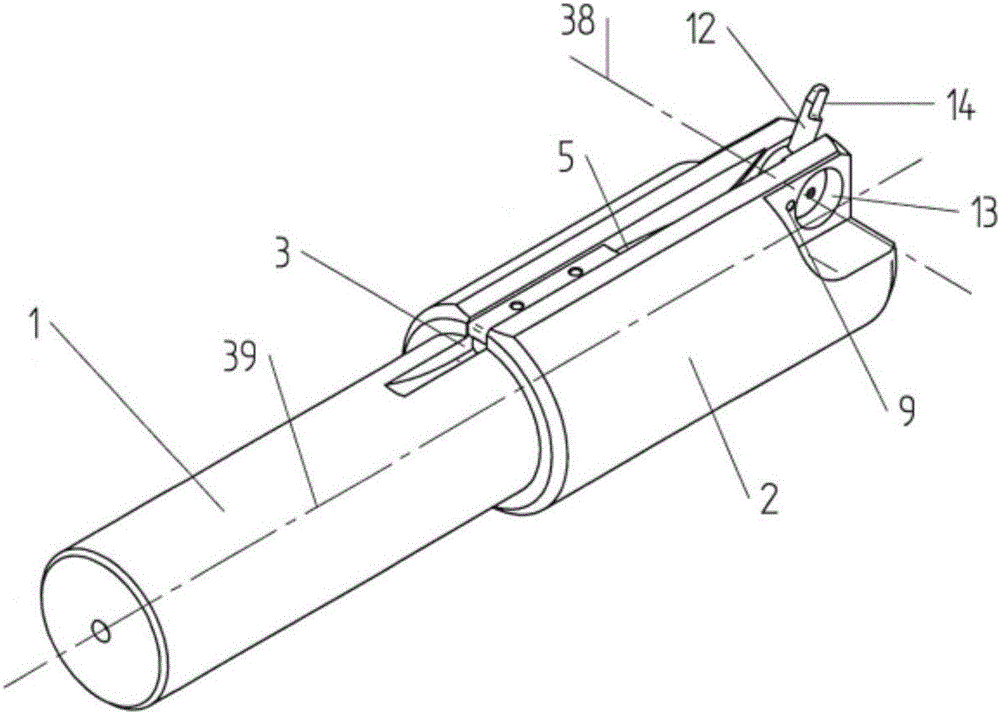
[0051] figure 1 The deburring tool according to the invention in , consists essentially of a cylindrical tool shaft 1 , to which a base body 2 is fastened in one or more parts. A longitudinal groove 3 is machined into the base body 2 on one side on the outer circumference of the base body 2 and extends from the rear part of the base body 2 to the front end face 37 .

[0052] according to Figure 5 , clamped in the region of the longitudinal groove 3 is a bending spring 5 , the rear end of which is held by the clamping strip 4 . The clamping strip 4 is fastened in the region of the base body 2 by means of clamping screws 16 , so that the rear end of the bending spring 5 is clamped in the rear part of the base body 2 .

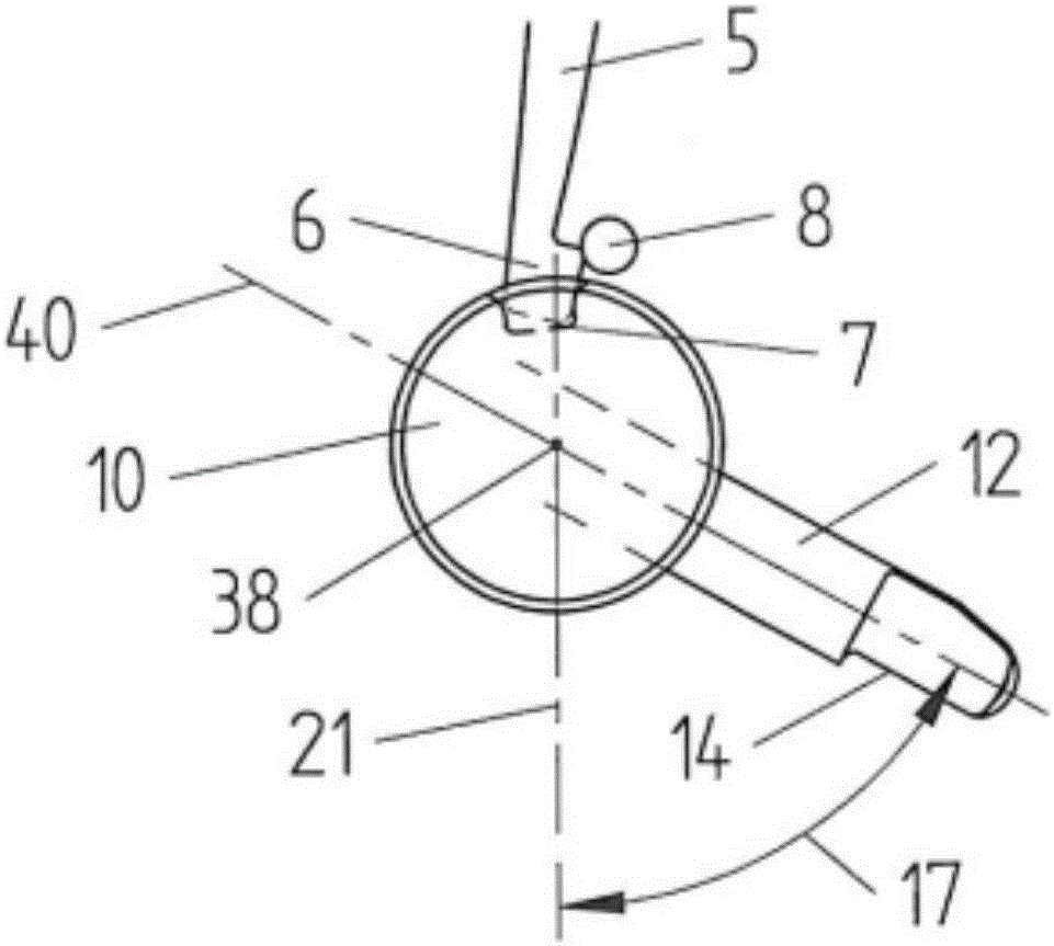
[0053] The free end of the front part of the bending spring 5 according to Figure 5 Engages in a radially deepened groove 7 machined at the outer circumference of the tool holder 10 and is immovably supported there.

[0054] Tool holder 10 of preferably cyl...


PUM


Abstract

Deburring tool for deburring of nonround contours on workpieces (22) consisting of a tool shaft (1) for fastening in a path guiding machine (32), which is suitable to guiding the deburring tool (1, 2) by its machine movement (29, 30, 33) along a workpiece contour (24) which is nonround in at least the radial direction, wherein at least one deburring blade (12) having at least one cutting edge (14) is pressed under spring loading against the workpiece contour (24) in chip removing manner and can be moved along the workpiece contour (24).

Description

technical field [0001] The invention relates to a deburring tool for deburring non-circular contours on workpieces according to the preamble of patent claim 1 . Background technique [0002] The object of EP 0 446 767 B1 is known as a deburring tool of the type mentioned above, which works with a spring-loaded reversible trimming knife. The deburring tool is rotationally driven on the tool shaft and has a rotational speed in the range of 500 to 10,000 revolutions per minute. [0003] The deburring effect is correspondingly achieved by the rotational movement of the deburring tool about the axial axis of the cylindrical bore, wherein only the edges of the cylindrical bore directed axially forwards and backwards can be deburred. Such deburring tools are not suitable for the deburring of non-circular recesses or non-circular borehole diameters in the radial direction of the borehole. [0004] The same disadvantages also apply to EP 2 161 090 A2, although a deburring tool for ...

Claims


Application Information

Patent Timeline
Patent Type & Authority Applications(China)
IPC IPC(8): B23D79/02
CPCB23D79/02
Inventor 哈里·斯图德
Owner HEULE WERKZEUG
Why Eureka
Try Eureka