Heat insulating device for engine compartment and passenger compartment of car

An engine compartment and heat insulation device technology, applied in the directions of engine components, machines/engines, charging systems, etc., can solve the problems that the heat of the engine compartment cannot be conducted to the passenger compartment, and the heat insulation effect is limited, so as to improve the use economy, The effect of reducing energy consumption and ensuring comfort

Inactive Publication Date: 2016-09-07
LIAONING UNIVERSITY OF TECHNOLOGY
View PDF5 Cites 0 Cited by
  • Summary
  • Abstract
  • Description
  • Claims
  • Application Information

AI Technical Summary

Problems solved by technology

[0003] In order to overcome the problem of limited heat insulation effect of the existing method, the invention proposes a heat insulation device for the engine compartment and the passenger compartment
Under the premise of not increasing the engine load and the air resistance of the whole vehicle, the device prevents the heat from the engine compartment from be

Method used


Image

  • Heat insulating device for engine compartment and passenger compartment of car

Examples


Embodiment Construction

[0018] The invention will be further described below in conjunction with the accompanying drawings.

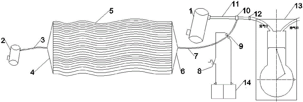
[0019] A heat insulation device for an automobile engine compartment and a passenger compartment, such as figure 1 As shown, it includes: thin tube array 5, auxiliary air filter 3, auxiliary air intake pipe I3, auxiliary air intake pipe II7, auxiliary pipeline interface 10 and temperature control solenoid valve device; the temperature control solenoid valve device includes a power supply 14. The temperature control switch 8 and the solenoid valve 9, wherein the power supply 14 is a car battery.

[0020] The auxiliary air filter 2 is located at the end of the auxiliary air intake pipeline away from the engine, and is used for filtering the air entering the engine through the auxiliary air intake branch. The auxiliary air intake pipe I3 ​​is distributed between the auxiliary air filter 2 and the transition connection I4, and the auxiliary air intake pipe II7 is located between ...


PUM


Abstract

A heat insulating device for an engine compartment and a passenger compartment of a car is arranged on a separating plate between the engine compartment and the passenger compartment and comprises a thin pipe array, an auxiliary air filter, an auxiliary air inlet pipe I, an auxiliary air inlet pipe II, an auxiliary pipeline connecting port and a temperature-control solenoid valve device, wherein one end of the thin pipe array is connected with the auxiliary air inlet pipe I by the aid of a transitional coupling I; the auxiliary air inlet pipe I is connected with one end of the auxiliary air filter; the other end of the auxiliary air filter communicates with the atmosphere; the other end of the thin pipe array is connected with the auxiliary air inlet pipe II by the aid of a transitional coupling II; and the auxiliary air inlet pipe II is connected with an original air inlet pipe of an engine by the aid of the auxiliary pipeline connecting port. Under the effect of negative pressure in the air inlet pipe of the engine, air in thin pipes of the thin pipe array of the heat insulating device flows, so that heat insulation of the engine compartment and the passenger compartment is realized. With the adoption of the heat insulating device, on the premise that the load of the engine and air resistance of the whole car are not increased, heat of the engine compartment cannot be transferred to the passenger compartment, so that the problem of reduction of riding comfort of the passenger compartment due to transfer of the heat of the engine is solved; meanwhile, the heat of the engine compartment is prevented from being transferred to the passenger compartment, and thus the energy consumption of an air conditioner of the car can also be reduced to a certain extent.

Description

technical field [0001] The invention relates to a thermal insulation device for an automobile engine compartment and a passenger compartment, which is mainly applied to passenger cars and cars with rear engines. Background technique [0002] At present, most of the medium and large passenger cars and a small number of cars adopt the rear engine structure. With the extension of the working time of the car engine, the temperature in the engine compartment will gradually rise, and the heat in the engine compartment will pass through the gap between the engine compartment and the passenger compartment. The bulkhead is transmitted to the passenger compartment, causing the temperature of the passenger compartment to rise (especially the temperature near the floor of the upper passenger compartment of the engine compartment, which can reach 40°C to 50°C). An increase in the temperature of the passenger compartment will reduce the ride comfort of the occupants, and at the same time ...

Claims


Application Information

Patent Timeline
IPC IPC(8): F02M35/10F02B77/11
CPCF02B77/11F02M35/10209F02M35/10268
Inventor 刘树伟周武奎
Owner LIAONING UNIVERSITY OF TECHNOLOGY
Why Eureka
Try Eureka