
Fixed MPO optical fiber head clamping device

A technology of optical fiber head and holder, which is applied in the direction of light guide, optics, instrument, etc., can solve the problems of different shapes of optical fiber head, and achieve the effect of easy removal

Inactive Publication Date: 2016-09-07
WUXI HI NANO TECH
View PDF6 Cites 0 Cited by
  • Summary
  • Abstract
  • Description
  • Claims
  • Application Information

AI Technical Summary

Problems solved by technology

However, in the prior art, different types of optical fiber heads have different shapes, how to conveniently fix the optical fiber head is a very practical problem

Method used


Image

  • Fixed MPO optical fiber head clamping device

Examples


Embodiment Construction

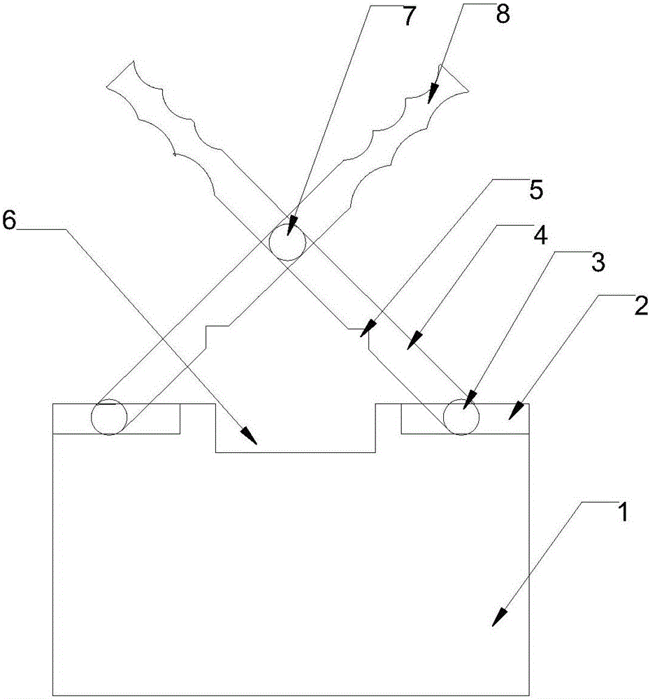
[0009] Such as figure 1 As shown, the present invention includes a base 1, the upper surface of the base 1 is provided with a track 2 and a square notch 6; the track 2 is arranged at both ends of the square notch 6; two spanners 4 intersecting each other are also provided; two intersecting spanners 4 The wrench 4 is fixed to each other through the shaft 7; the first end of the wrench 4 is provided with a track end 3, which is embedded in the track 2; a triangular notch 5 is arranged between the track end 3 and the shaft 7; the second end of the wrench 4 is set There are multiple arc-shaped gaps 8 .

[0010] When in use, the arc-shaped notch 8 can be used for holding, and the two intersecting spanners 4 can rotate around the axis 7. If the two intersecting spanners 4 are moved inwardly, the track end 3 will slide inwardly, and the two triangular The notch 5 is separated from the square notch 6, and the optical fiber head can be put into the square notch 6 or taken out of the s...


PUM


Abstract

The invention discloses a fixed MPO optical fiber head clamping device, which comprises a pedestal and is characterized in that the upper surface of the pedestal is provided with a track and a square notch; the track is arranged at two ends of the square notch; the upper surface of the pedestal is further provided with two intercrossed wrenches; the two intercrossed wrenches are mutually fixed through a shaft; a first end of each wrench is provided with at track terminal which is embedded into the track; a triangular notch is arranged between the track terminal and the shaft; and a second end of each wrench is provided with a plurality of arc-shaped notches. The fixed MPO optical fiber head clamping device disclosed by the invention can be matched with a PC-model optical fiber head, clamps the optical fiber head in a fixed manner, is applicable to installation, cleaning and the like of the optical fiber head, and is very convenient to clamp and take down.

Description

technical field [0001] The invention relates to the field of optical fiber communication, in particular to a fixed MPO optical fiber head holder. Background technique [0002] In the prior art, when performing production tests on optical fibers, it is often encountered that the optical fiber head needs to be fixed in a certain position to facilitate its inspection and testing. However, in the prior art, different types of fiber optic heads have different shapes, and how to conveniently fix the fiber optic heads is a very practical problem. The outer circumference of the fiber optic head of the FC model is approximately a rectangular cylinder, and the long section is small in size. In order to make it convenient and firm when fixed, and easy to disassemble when disassembled, it is necessary to design a fiber optic head clip that matches its model. Holder. Contents of the invention [0003] Aiming at the deficiencies of the prior art, the invention discloses a fixed MPO op...

Claims


Application Information

Patent Timeline
Patent Type & Authority Applications(China)
IPC IPC(8): G02B6/36
CPCG02B6/3624
Inventor 吕耀安
Owner WUXI HI NANO TECH
Learn More