A grid voltage phase-locking method and system

A grid voltage and phase-locked technology, applied to electrical components, circuit devices, AC network circuits, etc., can solve problems such as lowering system reliability, PI controller phase-locked loop frequency fluctuations, and inability to intuitively obtain grid voltage angular velocity, etc. , to achieve the effect of convenient power grid voltage angular velocity, high phase-locking precision, and convenience

Active Publication Date: 2018-03-09
SANY ELECTRIC CO LTD
View PDF6 Cites 1 Cited by
  • Summary
  • Abstract
  • Description
  • Claims
  • Application Information

AI Technical Summary

Problems solved by technology

However, this technical solution has the following problems: (1) The phase-locked method is equivalent to open-loop control, and its precision is not as high as that of closed-loop control using PI control
(2) The phase-locked result is the angle information of the grid voltage, and the angular velocity of the grid voltage is not intuitively obtained
Therefore, in the traditional software phase-locking method, the output fluctuation of the PI controller will cause the frequency of the phase-locked loop output to fluctuate. If the fluctuation is too large, the reliability of the entire system will inevitably be reduced.

Method used


Image

  • A grid voltage phase-locking method and system
  • A grid voltage phase-locking method and system
  • A grid voltage phase-locking method and system

Examples


Embodiment Construction

[0048] The preferred embodiments of the present invention will be described in detail below in conjunction with the accompanying drawings, so that the advantages and features of the present invention can be more easily understood by those skilled in the art, so as to define the protection scope of the present invention more clearly.

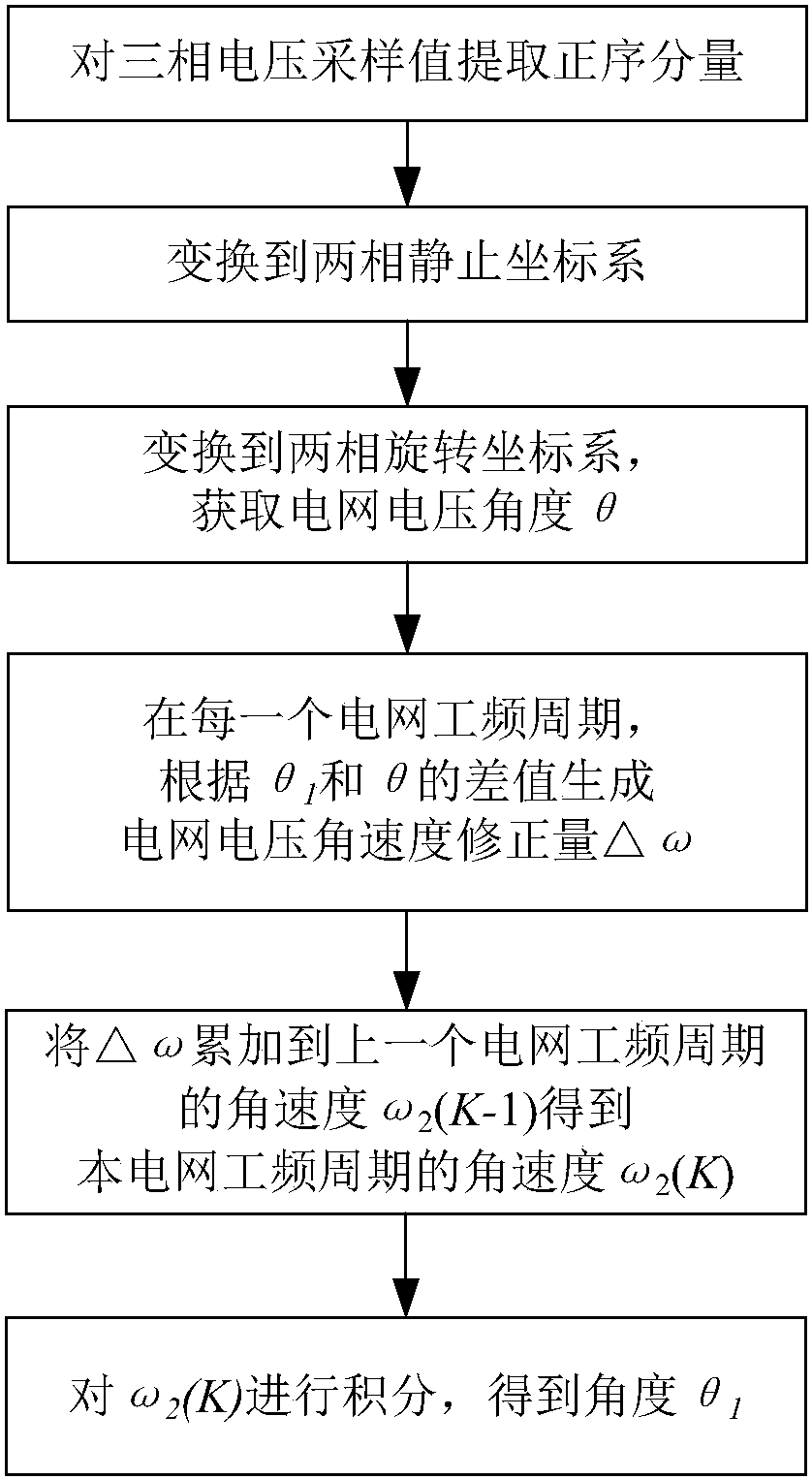
[0049] Such as image 3 As shown, the steps of the grid voltage phase-locking method in this embodiment include:

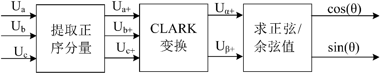
[0050] 1) The sampling value of the three-phase voltage (U a , U b , U c ) to extract the positive sequence components to get U a+ , U b+ , U c+ ;

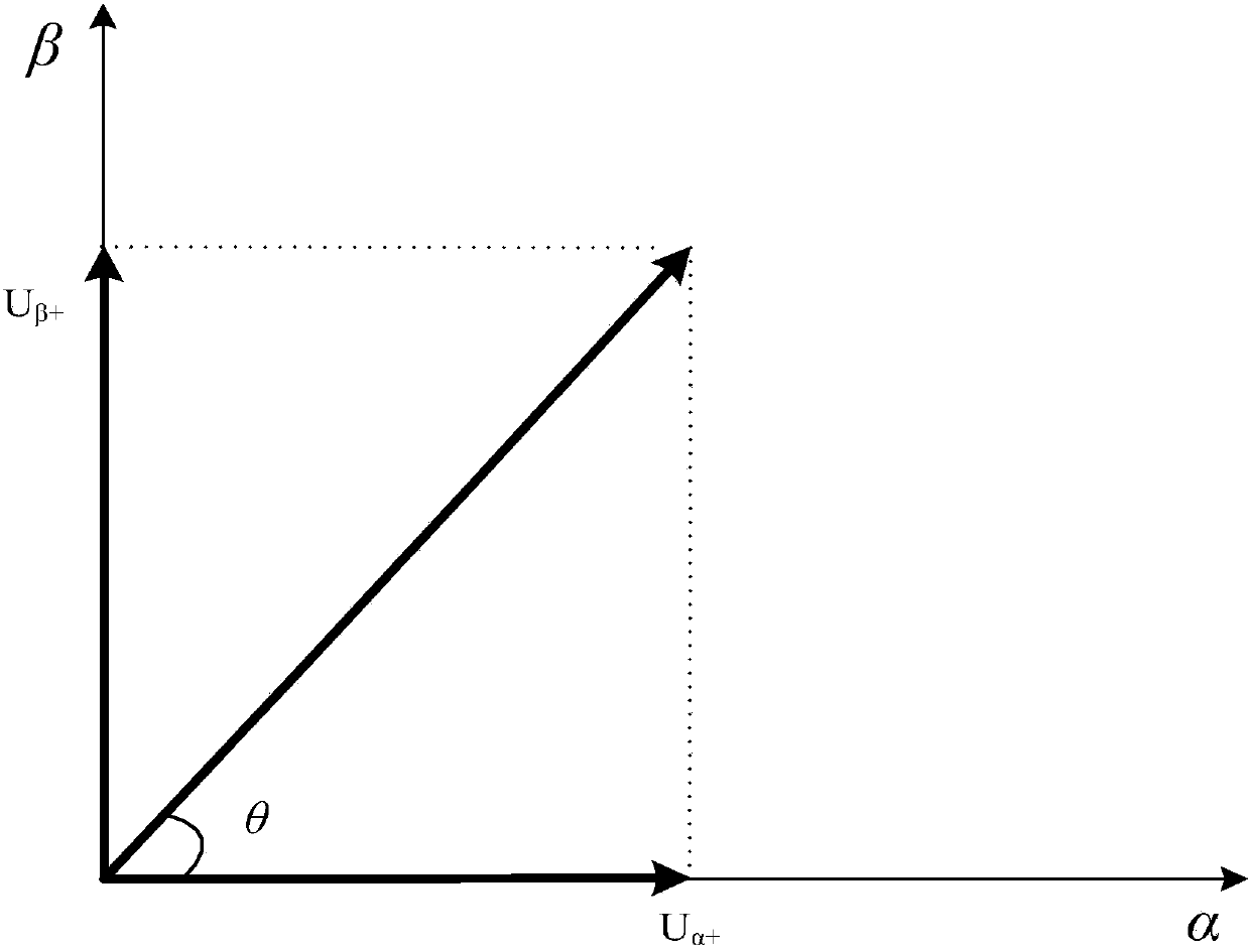
[0051] 2) The extracted positive sequence component (U a+ , U b+ , U c+ ) into the αβ two-phase stationary coordinate system, and get U α+ and U β+ ;

[0052] 3) The voltage components in the αβ two-phase stationary coordinate system (get U α+ and U β+ ) to dq two-phase rotating coordinate system (get U d and U q ), according to the voltage component transformed to the dq...


PUM


Abstract

The invention discloses a power grid voltage phase-locking method and system. The phase-locking method comprises the following steps: extracting positive-sequence component from a three-phase voltage sampling value, converting to a two-phase rotational coordinate system and computing a power grid voltage angle theta; computing a power grid voltage angle speed correction delta Omega according to the difference value of the phase-locking output angle theta1 and the power grid voltage angle theta computed by a sampling period at this time at every power grid frequency period, and accumulating to the power grid voltage angle speed Omega2(K-1) at the former power grid frequency period to obtain the Omega2(K) of this power grid frequency period and integrating to obtain the phase-locking output angle theta1; the system comprises a positive-sequence component extracting unit, a two-phase static coordinate system conversion unit, a power grid voltage angle computing unit and a phase-locking output angle computing unit. Through the adoption of the method disclosed by the invention, the advantages of being high in phase-locking precision and fast in dynamic response of the traditional software phase-locking method are retained, and the influence of the frequency value fluctuation of the phase-locking output to the system performance is reduced; the phase-locking precision is high, and the power grid voltage angle speed is convenient to obtain.

Description

technical field [0001] The invention relates to PWM conversion technology, in particular to a grid voltage phase-locking method and system. Background technique [0002] In the field of PWM converters, it is necessary to obtain the grid voltage phase and frequency through phase-locking for corresponding calculation and control. The commonly used phase-locking methods can be divided into two categories, hardware phase-locking and software phase-locking. Hardware phase-locking usually needs to judge the zero-crossing point of the grid voltage, calculate the period value of the grid voltage, and then calculate the frequency and phase of the grid voltage. This method needs to be calculated once in a cycle, and the dynamic response is slow. The usual method of software phase-locking is: transform the three-phase input voltage into the dq two-phase rotating coordinate system through Park, and adjust the q-axis or d-axis (according to the actual transformation) component to zero ...

Claims


Application Information

Patent Timeline
Patent Type & Authority Patents(China)
IPC IPC(8): H02J3/00H02M1/00
CPCH02J3/00H02M1/00
Inventor 刘洁刘光欣史建英
Owner SANY ELECTRIC CO LTD
Why Eureka
Try Eureka