Belt conveyor tensioning device

A belt conveyor and tensioning device technology, applied in the field of transmission machinery, can solve problems such as inability to adjust the conveyor belt, time-consuming and labor-intensive, and reduced production efficiency

Active Publication Date: 2018-06-26
JIANGHAN UNIVERSITY
View PDF6 Cites 0 Cited by
  • Summary
  • Abstract
  • Description
  • Claims
  • Application Information

AI Technical Summary

Problems solved by technology

[0004] At present, the tensioning wheel is usually used to adjust the tension of the conveyor belt. It is not only time-consuming and laborious to adjust the tensioning wheel, but also the conveyor belt cannot be adjusted quickly, which reduces the production efficiency.

Method used


Image

  • Belt conveyor tensioning device
  • Belt conveyor tensioning device

Examples


Embodiment Construction

[0032] In order to make the object, technical solution and advantages of the present invention clearer, the implementation manner of the present invention will be further described in detail below in conjunction with the accompanying drawings.

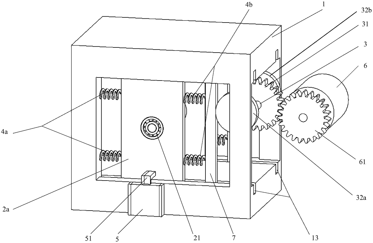
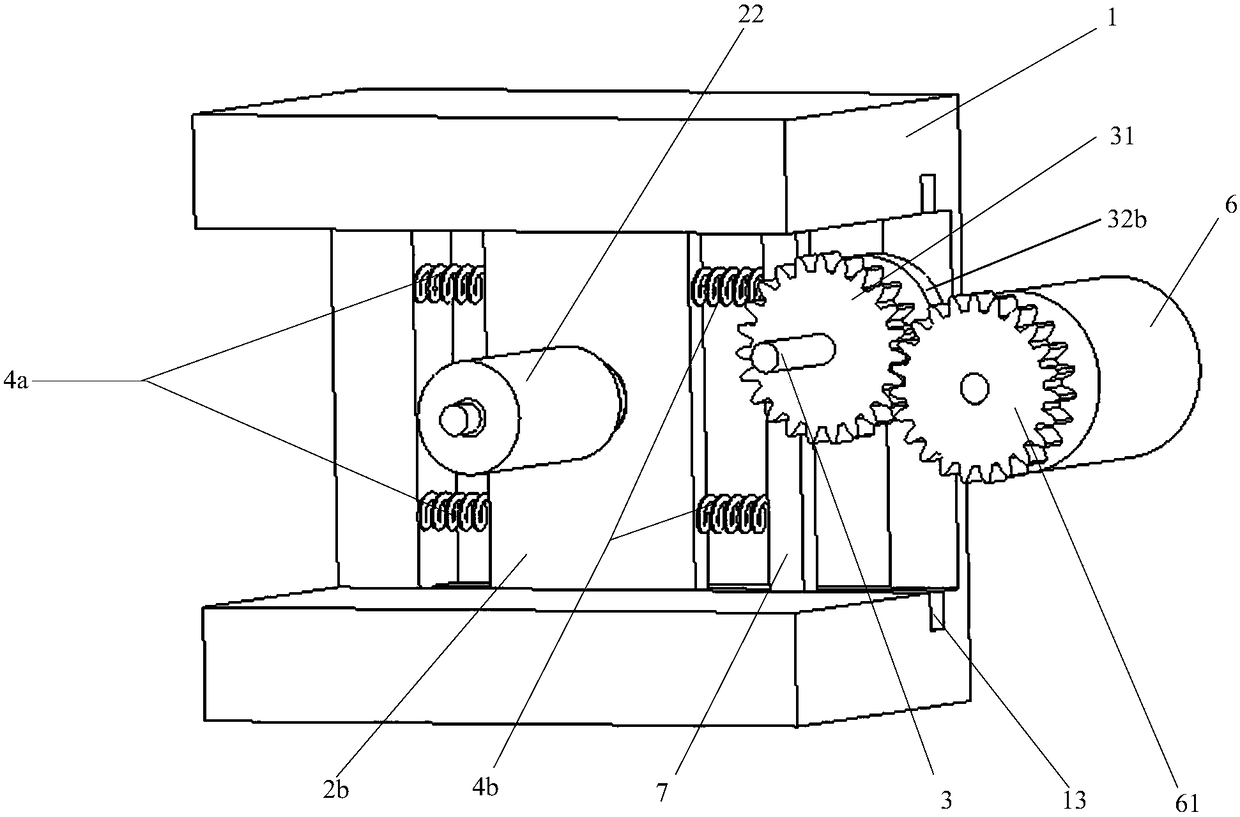
[0033] figure 1 It is a structural schematic diagram of a belt conveyor tensioning device provided by an embodiment of the present invention, figure 2 yes figure 1 The schematic diagram of the internal structure of the belt conveyor tensioning device shown, combined with figure 1 with figure 1 , the device includes a frame 1, a slide plate, a roller 22, a first elastic element 4a, a push plate 7, a second elastic element 4b, a first cam 32a, a gear 31, a motor 6, an output gear 61, and is used to control the motor 6 The rotating control box 5 and the sliding contact 51 for connecting the circuit of the control box 5, the sliding plate includes a first sliding plate 2a and a second sliding plate 2b, and the first sliding plate 2a an...


PUM


Abstract

The invention discloses a belt conveyor tensioning device, which belongs to the field of transmission machinery. The device includes a frame, a sliding plate, a roller, a first elastic element, a push plate, a second elastic element, a first cam, a control box and a sliding contact. When a large load occurs on the conveyor belt, the first sliding plate and The second sliding plate slides sideways, so that the first elastic element is further compressed, the sliding contact slides, the circuit of the control box is connected to make the cam rotate, and the second elastic element moves the pushing plate to the side away from the sliding plate. Translating the control box on one side makes the cam continue to rotate, and the compression amount of the second elastic element continues to decrease, so that the first elastic element pushes the sliding plate to slide to a suitable position. When the load on the conveyor belt becomes smaller, the sliding contact turns on the control The circuit of the box makes the cam reverse, the second elastic element is compressed, and pushes the sliding plate to slide to the side of the first elastic element, thereby realizing the adjustment of the tightness of the conveyor belt.

Description

technical field [0001] The invention relates to the field of transmission machinery, in particular to a belt conveyor tensioning device. Background technique [0002] A conveyor is a material handling machine that continuously conveys materials on a certain route, also known as a continuous conveyor. The conveyor can carry out horizontal and inclined conveying, and can also form a space conveying line, and the conveying line is generally fixed. Due to the large conveying capacity and long transport distance of the conveyor, it can also complete several process operations at the same time during the conveying process, so it is widely used. [0003] Most of the existing conveyors are belt conveyors, that is, by placing the materials on the conveyor belt, the motor rotates to drive the conveyor belt to move, and the materials are transported to the designated position. In order to ensure the smooth transportation of materials, the conveyor belt should be as tight as possible ...

Claims


Application Information

Patent Timeline
Patent Type & Authority Patents(China)
IPC IPC(8): B65G23/44
CPCB65G23/44
Inventor 易建钢王雄
Owner JIANGHAN UNIVERSITY
Why Eureka
Try Eureka