Method for monitoring absolute earth surface deformations of depression area by means of rising rail InSAR and falling rail InSAR without ground support

A surface deformation and subsidence area technology, applied in radio wave measurement systems, radio wave reflection/re-radiation, measurement devices, etc. Reflect on land subsidence and other issues

Active Publication Date: 2016-09-14
CENT SOUTH UNIV
View PDF5 Cites 19 Cited by
  • Summary
  • Abstract
  • Description
  • Claims
  • Application Information

AI Technical Summary

Problems solved by technology

Obviously, this method cannot obtain the absolute deformation results of the surface for the case where the deformation affected area is large and the stable point cannot be found. For details, see reference [3]
[0004] From the above analysis, it can be seen that for areas without ground control points, and the influence range of the surface deformation exceeds the coverage of the entire SAR image, then the existing methods cannot obtain the absolute deformation results of the ground surface
In practice, the above situation is very common. For example, in the face of large-scale land subsidence caused by the ex

Method used


Image

  • Method for monitoring absolute earth surface deformations of depression area by means of rising rail InSAR and falling rail InSAR without ground support
  • Method for monitoring absolute earth surface deformations of depression area by means of rising rail InSAR and falling rail InSAR without ground support
  • Method for monitoring absolute earth surface deformations of depression area by means of rising rail InSAR and falling rail InSAR without ground support

Examples


Embodiment Construction

[0039] The present invention will be further described below in conjunction with the accompanying drawings and embodiments.

[0040] In order to facilitate understanding of the present invention, at first the theoretical basis of the present invention is provided:

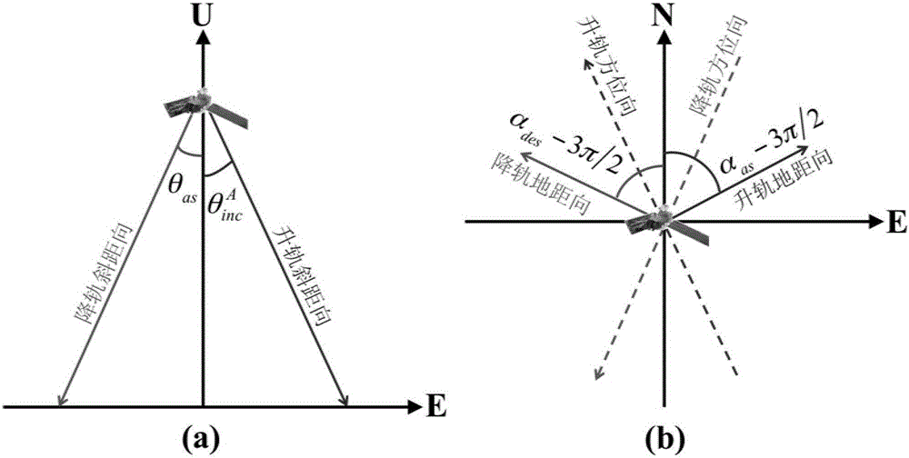
[0041] As we all know, the direct consequence of geological disasters is the deformation of the earth's surface. For InSAR technology, it can only monitor ground observation points x i The relative deformation relative to a reference point in the upward slope distance, namely

[0042] D. rat (x i ) = D real (x i )+K (1)

[0043] Among them, D rat (x i ) is the ground observation point x i InSAR slant-range relative deformation measurements on ; D real (x i ) is the ground observation point x i K is the constant difference between the InSAR slant distance relative deformation measurement and the slant distance absolute deformation, that is, the absolute offset.

[0044] In practice, however, surface def...


PUM


Abstract

The invention discloses a method for monitoring absolute earth surface deformations of a depression area by means of a rising rail InSAR and a falling rail InSAR without ground support. The method comprises the steps that relative earth surface deformation measured values of the earth surface in two different slope distance directions are obtained by means of data of the rising rail InSAR and data of the falling rail InSAR; relative deformations of the earth surface in the vertical direction and in the longitudinal direction are estimated by fusing relative deformation fields of the rising rail InSAR and the falling rail InSAR; absolute offsets of the relative deformation measured values of the rising rail InSAR and the falling rail InSAR are calculated by means of ground points of which relative deformation magnitudes in the longitudinal direction are smaller than a certain threshold; the absolute deformations of the earth surface in the vertical direction and in the longitudinal direction are estimated by means of the rising rail InSAR deformation value and the falling rail InSAR deformation value which are corrected through the absolute offsets. The technique bottleneck that a traditional InSAR only can obtain the relative earth surface deformations is broken through, and the absolute deformation results of the earth surface in the vertical direction and the longitudinal direction can be obtained without laying ground control points or assuming a far field deformation to be zero.

Description

technical field [0001] The invention belongs to the field of geodetic surveying based on remote sensing images, and in particular relates to a method for monitoring absolute surface deformation in a subsidence area using a lifting rail InSAR without ground assistance. Background technique [0002] Synthetic Aperture Radar Interferometry (InSAR) technology is a space geodetic and remote sensing method developed in recent decades. It is used for monitoring surface deformation caused by geological disasters such as earthquakes, volcanic eruptions, glacier drift, landslides, and debris flows. Especially with the increasing maturity of multi-temporal InSAR technology (such as permanent scatterers and short baseline set technology), it is possible to conduct joint analysis on the time-series SAR images acquired in the same orbit, thereby better suppressing the terrain residual in the InSAR interferogram , Atmospheric delay and loss of correlation noise, etc., further improve the ...

Claims


Application Information

Patent Timeline
IPC IPC(8): G01S13/90
CPCG01S13/90G01S13/9023
Inventor 胡俊孙倩李志伟朱建军
Owner CENT SOUTH UNIV
Why Eureka
Try Eureka