
Exciter used for active vibration-reduction and vibration damper provided with same

A technology of active vibration reduction and vibration exciter, applied in the direction of fluid using vibration, etc., can solve the problems of narrow output range of excitation force, inconvenient adjustment, small output force of electromagnetic vibration exciter, etc., and achieve large output force characteristics Effect

Active Publication Date: 2016-09-21
中国船舶集团有限公司第七一一研究所
View PDF6 Cites 2 Cited by
  • Summary
  • Abstract
  • Description
  • Claims
  • Application Information

AI Technical Summary

Problems solved by technology

[0002] At present, most of the actively controlled vibrators are electromagnetic exciters, but the output force of electromagnetic exciters is small and the heat dissipation performance is not good. vibration requirements
[0003] Existing mechanical exciters mostly adopt single-axis structure and double-axis structure, among which the single-axis single eccentric block structure cannot adjust the output force
The mechanical exciter with a single-axis double eccentric block structure generally adopts the method of punching holes in the eccentric block and inserting fixed pins to adjust the output force. The adjustment of the output force is limited, and stepless adjustment cannot be realized. Directional output of output force cannot be achieved
The existing biaxial structure exciter uses two parallel connecting shafts to install two eccentric blocks respectively, which can realize directional output of output force, but the size of the eccentric block is limited by the arrangement of the connecting shafts and cannot be too large. The output range is narrow; and when adjusting the output force, the shell needs to be opened for manual adjustment, which is inconvenient to adjust

Method used


Image

  • Exciter used for active vibration-reduction and vibration damper provided with same
  • Exciter used for active vibration-reduction and vibration damper provided with same
  • Exciter used for active vibration-reduction and vibration damper provided with same

Examples


Embodiment Construction

[0031] The application will be further described in detail below in conjunction with the accompanying drawings and embodiments. It should be understood that the specific embodiments described here are only used to explain related inventions, rather than to limit the invention. It should also be noted that, for ease of description, only parts related to the invention are shown in the drawings.

[0032] It should be noted that, in the case of no conflict, the embodiments in the present application and the features in the embodiments can be combined with each other. The present application will be described in detail below with reference to the accompanying drawings and embodiments.

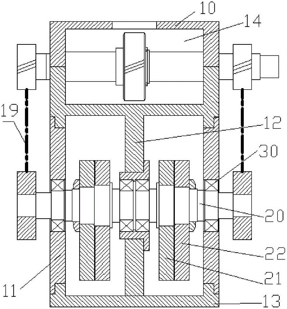
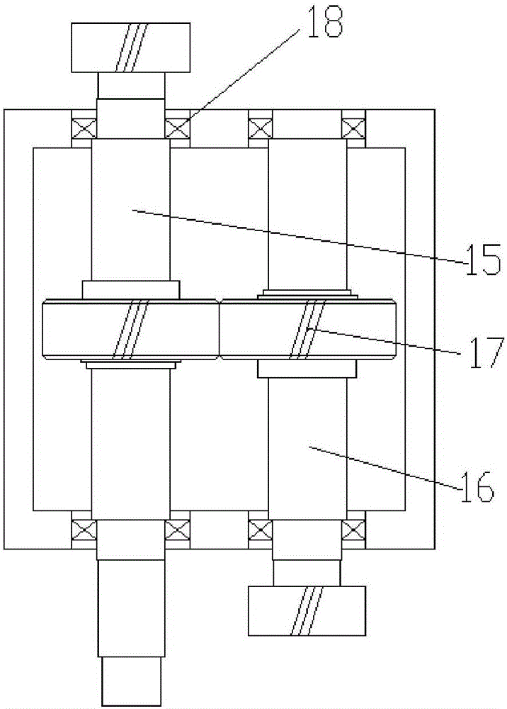
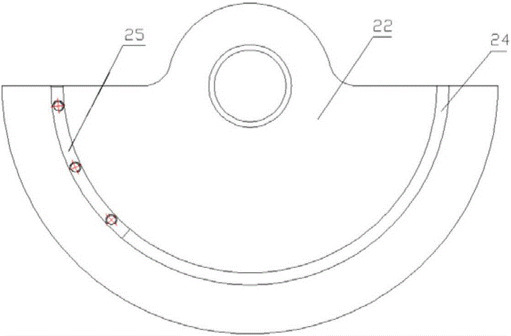
[0033] On the one hand, if figure 1 As shown, the application provides a vibrator for active vibration reduction, including a housing, a motor (not shown), and two connecting shafts 20 supported on the housing; the motor is used as a power source, and it is connected to the two Shaft transmission...


PUM


Abstract

The invention discloses an exciter used for active vibration-reduction and a vibration damper provided with the same. The exciter used for active vibration-reduction comprises a shell, a motor and two connecting shafts which are supported by the shell. The motor serves as a power source and is in transmission connection with the two connecting shafts; an eccentric block assembly is arranged on each connecting shaft; and the two connecting shafts are coaxially arranged and operate reversely to drive the eccentric block assemblies on the two connecting shafts correspondingly to operate reversely. The vibration damper is provided with the exciter used for active vibration-reduction. The exciter used for active vibration-reduction and the vibration damper provided with the same have the characteristic of large output force, stepless regulation for the output force can be conducted conveniently, and directional output of the force can be achieved.

Description

technical field [0001] The present disclosure relates to a vibrator, in particular to a vibrator for active vibration reduction and a vibration reduction device including the same. Background technique [0002] At present, the active control exciters are mostly electromagnetic exciters, but the output force of electromagnetic exciters is small and the heat dissipation performance is not good. vibration requirements. [0003] Existing mechanical exciters mostly adopt single-axis structure and double-axis structure, among which the single-axis single eccentric block structure cannot adjust the output force. The mechanical exciter with a single-axis double eccentric block structure generally adopts the method of punching holes in the eccentric block and inserting fixed pins to adjust the output force. The adjustment of the output force is limited, and stepless adjustment cannot be realized. The directional output of the output force cannot be realized. Existing exciters with...

Claims


Application Information

Patent Timeline
Patent Type & Authority Applications(China)
IPC IPC(8): B06B1/16
CPCB06B1/163
Inventor 张庆丰周文建张思明胡旭钢陈鹏叶林昌
Owner 中国船舶集团有限公司第七一一研究所
Learn More