Gear shock excitation mechanism

A vibration-exciting mechanism and gear technology, which is applied in the direction of gear transmission, belt/chain/gear, mechanical equipment, etc., can solve the problems of reduced service life, vibration bearing can not bear the excitation force, etc., to reduce oil temperature, bearing load The effect of increased capacity and long service life

Inactive Publication Date: 2012-10-10
潘国梁
View PDF0 Cites 3 Cited by
  • Summary
  • Abstract
  • Description
  • Claims
  • Application Information

AI Technical Summary

Problems solved by technology

[0004] The purpose of the present invention is to provide a gear excitation mechanism to solve the problem that the vibration bearing is limited by the excitation force, the vibration bearing cannot bear a larger excitation force, and reduce the service life to increase the excitation force

Method used


Image

  • Gear shock excitation mechanism
  • Gear shock excitation mechanism
  • Gear shock excitation mechanism

Examples


Embodiment 1

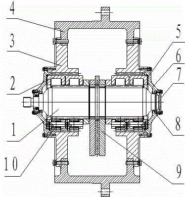
[0027] Embodiment 1: The gear excitation mechanism has a sun gear shaft 1, one end of the sun gear shaft 1 is connected to the external drive mechanism through a spline, the two ends of the sun gear shaft 1 are connected to the large end cover 6 through a sliding bearing 8, and the sun gear shaft 1 is connected to the large end cover 6. There are gears; the sun gear shaft 1, the planetary gear 10 and the inner gear 3 mesh with each other, the outer end of the inner gear 3 is connected with the working device 4, and the planetary gear 3 is installed on the planetary gear frame 2; the center hole of the fixed eccentric block 21 is the inner Gear is contained on the sun gear shaft 1 and is integrated with the sun gear shaft 1. The sliding sleeve center hole is the sliding sleeve internal gear 23, and the movable eccentric block 22 is contained on the outer circle of the sliding sleeve, and the movable eccentric block 22 can rotate around the sliding sleeve.

[0028] There are 4 pl...

Embodiment 2

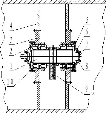
[0042] Embodiment 2: The planetary gear mechanism can be installed in the box to become an independent gear vibration mechanism, and there are retaining rings between the planetary gear frames, both of which play the role of isolating adjacent parts. Sliding bearings are installed at both ends of the sun gear shaft. The working device is a wheel, and an oil filling hole is arranged on the working device.

[0043] There are 2 planetary gear carriers 2, and there are retaining rings between every two planetary gear carriers; there are 3 to 6 planetary gears in each planetary gear carrier, and the planetary gears are installed on the planetary wheel carrier through shafts. Sliding bearings are installed on the shaft, and the end covers on both sides are installed on the inner gear.

[0044] A fixed eccentric block casting is installed on the sun gear shaft, and is separated from the planetary gear carrier by a retaining ring.

[0045] Other embodiment 1 is the same.

Embodiment 3

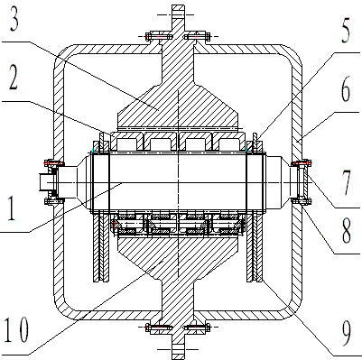
[0046] Embodiment 3: The eccentric mass mechanism is located on both sides of the planetary drive train. There are many sets of star gear mechanisms between the eccentric block mechanisms.

[0047] There are 6 planetary gear carriers 2, and there are retaining rings between every two planetary gear carriers; there are 3 to 6 planetary gears in each planetary gear carrier, and the planetary gears are installed on the planetary wheel carrier through shafts. Needle rollers or bearings or sliding bearings are installed on the shaft, and the end covers on both sides are installed on the inner gear. There is a gap between every two planetary gear carriers, and there is no gear ring. A sliding sleeve is arranged in the center hole of the fixed eccentric block.

[0048] The working device is a casing, and there is an oil filling hole on the working device.

[0049] Other embodiment 1 is the same.


PUM


Abstract

The invention discloses a gear shock excitation mechanism which belongs to a shock excitation mechanism applied to the engineering machinery. The gear shock excitation mechanism is provided with a sun wheel shaft, wherein one end of the sun wheel shaft is connected with an external drive mechanism through a spline, and the other end of the sun wheel shaft is connected to an end cover through a slide bearing; the sun wheel shaft is provided with a gear; the sun wheel shaft, a planetary wheel and an inner gear are meshed with each other; the outer end of the inner gear is connected with a working device; the planetary wheel is mounted on a planetary wheel frame; a central hole of a fixed eccentric block is an inner gear which is arranged on the sun wheel shaft and integrally connected with the sun wheel shaft. The central hole of a slide sleeve is an inner gear, and a movable eccentric block is arranged on the outer circle of the slide sleeve. The gear shock excitation mechanism has thefollowing advantages: 1, the shock excitation force is transferred among gears, and the bearing with great shock excitation force is not used; 2, a vibration shaft is connected with an eccentric block mechanism through a gear pair so as to meet the need for large-tonnage shock excitation force; 3, the oil temperature is reduced, and the working conditions of the vibration mechanism are improved; and 4, the service life is long, and the shock excitation force is much larger than that of the existing vibration mechanism.

Description

technical field [0001] The invention relates to a vibration excitation mechanism applied to engineering machinery, in particular to a gear vibration excitation mechanism. Background technique [0002] Existing vibration excitation mechanism: comprising a vibration shaft, a vibration bearing, a movable eccentric block and a fixed eccentric block, the vibration shaft is an optical axis, the two ends of the vibration shaft are connected with vibration bearings, the vibration shaft between the two vibration bearings There are two fixed eccentric blocks welded on the top to fix the vibration axis. There is a movable eccentric block between the two fixed eccentric blocks, which can rotate around the vibration axis; both the fixed eccentric block and the movable eccentric block are semicircular, and both have a center hole, and there is a hole at both ends of the diameter side of the fixed eccentric block , a follower shaft is connected to one of the holes; the diameter of the mov...

Claims


Application Information

Patent Timeline
Patent Type & Authority Patents(China)
IPC IPC(8): B06B1/16F16H1/32F16H1/46
Inventor 潘国梁
Owner 潘国梁
Why Eureka
Try Eureka